Hardware Components | Features and Specifications |
Ejector |
|
|
|
|
|
|
|
| S | FAIL | |
|
|
| Y | STATUS | |
|
|
| S | POWER | |
|
|
| T | ||
|
|
| RX ENET | ||
Reset Button |
|
| E | ||
|
| M | TX ENET | ||
|
|
|
|
| |
|
|
| 1 | 1 |
|
|
| DATA | NO SYNC | DATA | NO SYNC |
|
|
| 2 | 2 |
|
| A | C |
| ||
|
|
|
| ||
|
|
| 3 | 3 |
|
|
|
| 4 | 4 |
|
|
|
|
| E |
|
Console Terminal |
|
|
| T |
|
C |
|
| H |
| |
O |
|
| E |
| |
|
| R |
| ||
M |
|
|
| ||
|
|
| N |
| |
|
|
| E |
| |
|
|
| T |
| |
|
|
|
|
| |
|
| 1 |
|
| 1 |
|
| DATA | NO SYNC | DATA | NO SYNC |
|
| 2 |
|
| 2 |
| B | D |
| ||
|
|
|
| ||
|
| 3 |
|
| 3 |
|
| 4 |
|
| 4 |
Ejector |
|
|
|
|
|
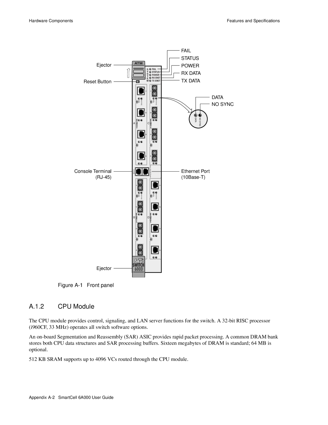
Figure A-1 Front panel
FAIL
STATUS
POWER
![]() RX DATA
RX DATA
TX DATA
| DATA |
| NO SYNC |
DATA | NO SYNC |
Ethernet Port
A.1.2 CPU Module
The CPU module provides control, signaling, and LAN server functions for the switch. A
An
512 KB SRAM supports up to 4096 VCs routed through the CPU module.
Appendix