Section 2. Installation and Hardware Set-Up
The
Before installation, it is necessary to set up the address of the
CAUTION Turn off the 12V supply and take static prevention precautions before removing the lid.
2.1 Setting the SDM Address
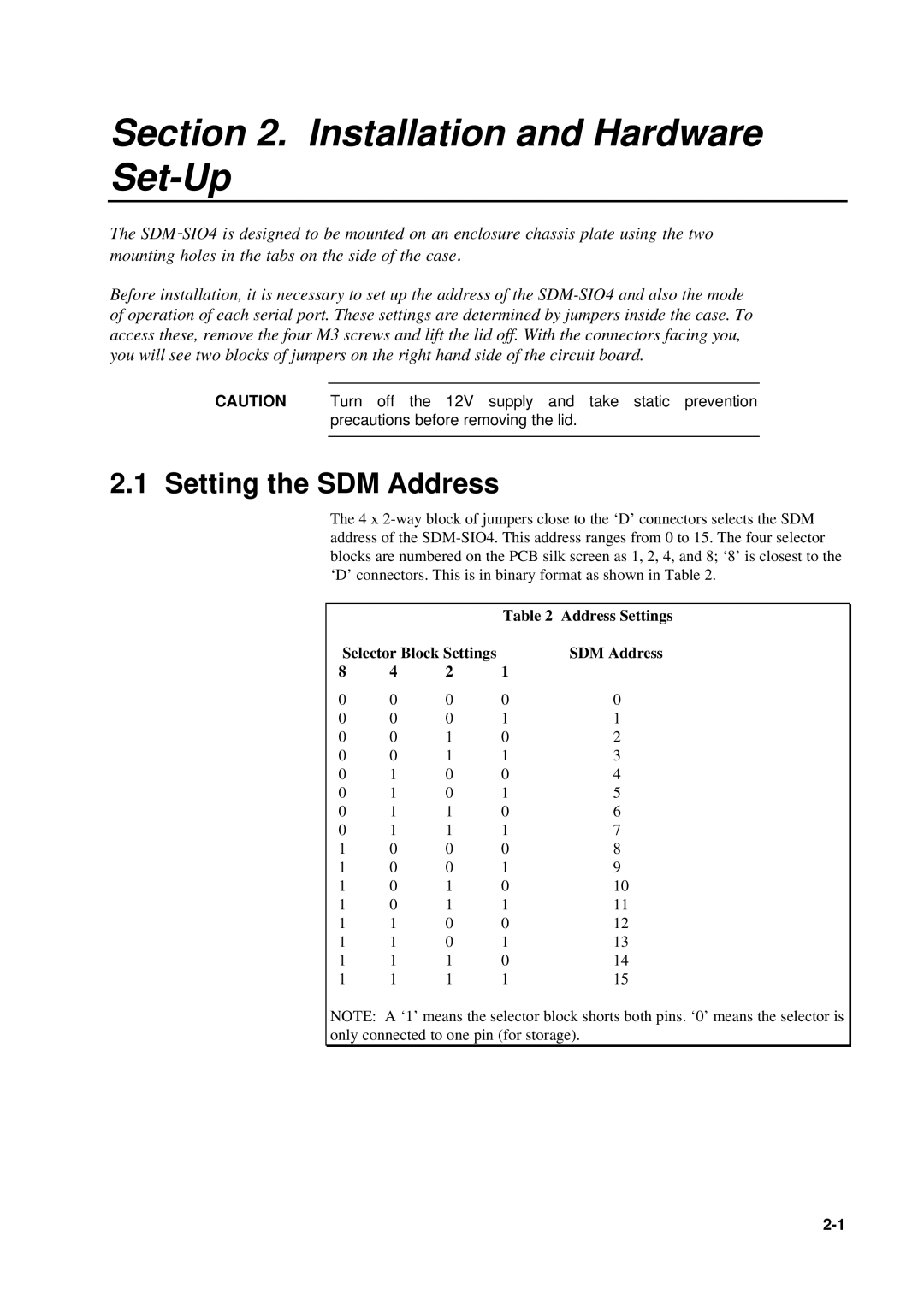
The 4 x
|
|
| Table 2 | Address Settings |
Selector Block Settings |
| SDM Address | ||
8 | 4 | 2 | 1 |
|
0 | 0 | 0 | 0 | 0 |
0 | 0 | 0 | 1 | 1 |
0 | 0 | 1 | 0 | 2 |
0 | 0 | 1 | 1 | 3 |
0 | 1 | 0 | 0 | 4 |
0 | 1 | 0 | 1 | 5 |
0 | 1 | 1 | 0 | 6 |
0 | 1 | 1 | 1 | 7 |
1 | 0 | 0 | 0 | 8 |
1 | 0 | 0 | 1 | 9 |
1 | 0 | 1 | 0 | 10 |
1 | 0 | 1 | 1 | 11 |
1 | 1 | 0 | 0 | 12 |
1 | 1 | 0 | 1 | 13 |
1 | 1 | 1 | 0 | 14 |
1 | 1 | 1 | 1 | 15 |
NOTE: A ‘1’ means the selector block shorts both pins. ‘0’ means the selector is only connected to one pin (for storage).