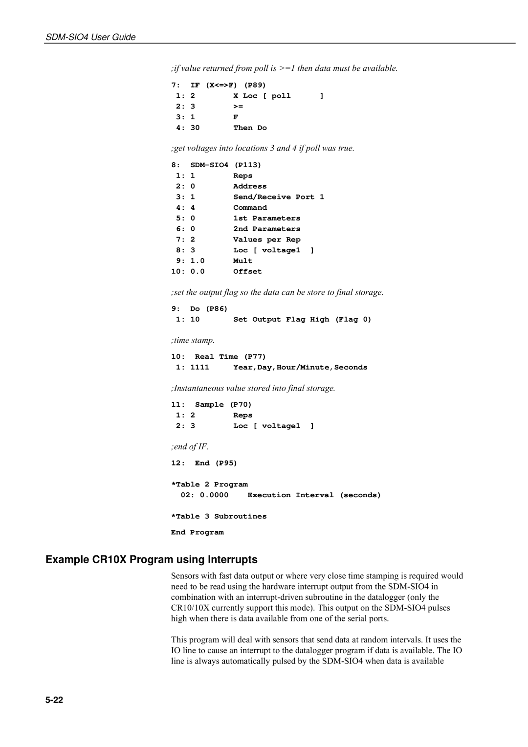
;if value returned from poll is >=1 then data must be available.
7:IF (X<=>F) (P89)
1: 2 | X Loc [ poll | ] | |
2: 3 | >= |
| |
3: | 1 | F |
|
4: | 30 | Then Do |
|
;get voltages into locations 3 and 4 if poll was true.
8:
1: 1 | Reps |
2: 0 | Address |
3: 1 | Send/Receive Port 1 |
4: 4 | Command |
5: 0 | 1st Parameters |
6: 0 | 2nd Parameters |
7: 2 | Values per Rep |
8:3 Loc [ voltage1 ]
9:1.0 Mult
10:0.0 Offset
;set the output flag so the data can be store to final storage.
9:Do (P86)
1:10 Set Output Flag High (Flag 0)
;time stamp.
10:Real Time (P77)
1: 1111 Year,Day,Hour/Minute,Seconds
;Instantaneous value stored into final storage.
11:Sample (P70)
1: | 2 | Reps |
2: | 3 | Loc [ voltage1 ] |
;end of IF.
12:End (P95)
*Table 2 Program
02: 0.0000 Execution Interval (seconds)
*Table 3 Subroutines
End Program
Example CR10X Program using Interrupts
Sensors with fast data output or where very close time stamping is required would need to be read using the hardware interrupt output from the
This program will deal with sensors that send data at random intervals. It uses the IO line to cause an interrupt to the datalogger program if data is available. The IO line is always automatically pulsed by the
