SERVICE
Do not remove the compressor terminal box cover until all electrical power is disconnected and pressure is relieved. Terminal pins may blow out causing injuries, death, and/or fire.
Service Notes
1.Where compressor components are shown, they are in normal order of removal from compressor.
2.For replacement items, use Carrier specified parts. See Carrier 06D Specified Parts list for compressor part interchangeability.
3.Before compressor is opened, the refrigerant must be removed from it by the Pumpdown method.
a.Start compressor, close suction shutoff valve, and reduce crankcase pressure to 2 psig (bypass low pressurestat with jumper).
b.Stop compressor and isolate from system by closing discharge shutoff valve.
c.Bleed any residual refrigerant. Drain oil if necessary.
4.After disassembly, clean all parts with solvent. Use mineral spirits, white gasoline or naphtha.
5.Before assembly, coat all parts with compressor oil and clean and inspect all gasket surfaces. Replace all gaskets with new standard specified gaskets, coated with compressor oil. See Table 5 for typical torque values.
6.After reassembly, evacuate compressor and open suction and discharge valves. Restart compressor and adjust refrigerant charge.
Table 5 — Torque Values
SIZE | THREADS | TORQUE |
| |
DIAM | RANGE | USAGE | ||
(in.) | PER IN. |
| ||
|
| |||
1/16 | 27 (pipe) | Pipe Plug — Crankshaft | ||
1/8 | 20 (pipe) | Oil Return Check Valve — | ||
Crankcase | ||||
|
|
| ||
| 20 (pipe) | Pipe Plug — Press. Gage Conn. | ||
| 20 | Connecting Rod Capscrew | ||
1/4 |
| Baffle Plate — Crankcase | ||
| 28 | Side Shield | ||
| Oil Pump Drive Segment | |||
|
| |||
|
| Unloader Valve | ||
|
| Cover Plate — Pump End | ||
|
| Bearing Head | ||
5/16 |
|
| ||
18 | Terminal Block Cap Screws | |||
|
| Suction Service Valve | ||
|
| Discharge Service Valve | ||
|
| Pump End Bearing Head | ||
3/8 | 16 | Bottom Plate — Crankcase | ||
Compressor Foot | ||||
|
| Cylinder Head | ||
|
| Motor End Cover — Crankcase | ||
7/16 | 14 | Motor End Cover — Crankcase | ||
1/2 | 13 | Suction Service Valve | ||
5/8 | 11 | Crankshaft Spinner Tube | ||
No. 10 | 32 | 4- 6 | Oil Pump Drive Segment | |
11/2 | 18 NEF | Oil Level Sight Glass |
LEGEND
NEF — National Extra Fine
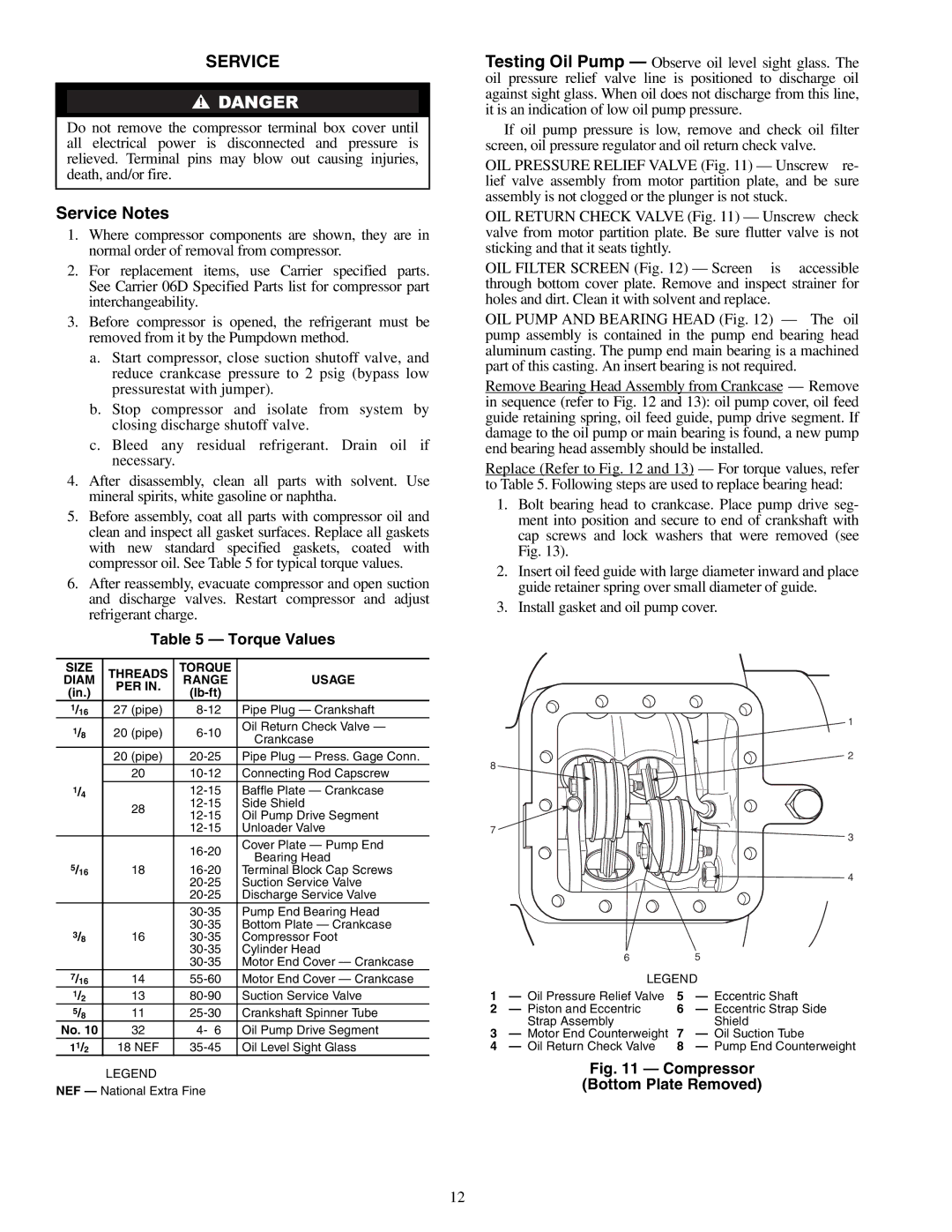
Testing Oil Pump — Observe oil level sight glass. The oil pressure relief valve line is positioned to discharge oil against sight glass. When oil does not discharge from this line, it is an indication of low oil pump pressure.
If oil pump pressure is low, remove and check oil filter screen, oil pressure regulator and oil return check valve.
OIL PRESSURE RELIEF VALVE (Fig. 11) — Unscrew re- lief valve assembly from motor partition plate, and be sure assembly is not clogged or the plunger is not stuck.
OIL RETURN CHECK VALVE (Fig. 11) — Unscrew check valve from motor partition plate. Be sure flutter valve is not sticking and that it seats tightly.
OIL FILTER SCREEN (Fig. 12) — Screen is accessible through bottom cover plate. Remove and inspect strainer for holes and dirt. Clean it with solvent and replace.
OIL PUMP AND BEARING HEAD (Fig. 12) — The oil pump assembly is contained in the pump end bearing head aluminum casting. The pump end main bearing is a machined part of this casting. An insert bearing is not required.
Remove Bearing Head Assembly from Crankcase — Remove in sequence (refer to Fig. 12 and 13): oil pump cover, oil feed guide retaining spring, oil feed guide, pump drive segment. If damage to the oil pump or main bearing is found, a new pump end bearing head assembly should be installed.
Replace (Refer to Fig. 12 and 13) — For torque values, refer to Table 5. Following steps are used to replace bearing head:
1.Bolt bearing head to crankcase. Place pump drive seg- ment into position and secure to end of crankshaft with cap screws and lock washers that were removed (see Fig. 13).
2.Insert oil feed guide with large diameter inward and place guide retainer spring over small diameter of guide.
3.Install gasket and oil pump cover.
1
![]()
![]() 2 8
2 8![]()
![]()
7 ![]()
3
![]() 4
4
| 6 |
| 5 |
| LEGEND | ||
1 | — Oil Pressure Relief Valve | 5 | — Eccentric Shaft |
2 | — Piston and Eccentric | 6 | — Eccentric Strap Side |
| Strap Assembly |
| Shield |
3— Motor End Counterweight 7 — Oil Suction Tube
4— Oil Return Check Valve 8 — Pump End Counterweight
Fig. 11 — Compressor
(Bottom Plate Removed)
12
