Install a solenoid valve (field supplied) in liquid line directly before expansion valve. Solenoid valve is necessary for single pumpout control used on 06D, 07D units. Refrigerant filter drier and moisture indicator are shipped with 07D condensing units for field installation. Install in liquid line according to manufacturer’s instructions.
Relief valve located on top of condenser (07D units) will open to relieve excessive pressure, allowing refrigerant to escape. Most local codes require piping from safety device to outdoors.
Refer to Carrier System Design Manual, Part 3, for standard piping techniques.
COMPRESSOR UNITS — Connect high- and
Install discharge line muffler (accessory) in discharge line as close to compressor shutoff valve as possible.
Electrical Connections
UNBALANCED
% Voltage Imbalance =
max voltage deviation from average voltage
100 x
average voltage
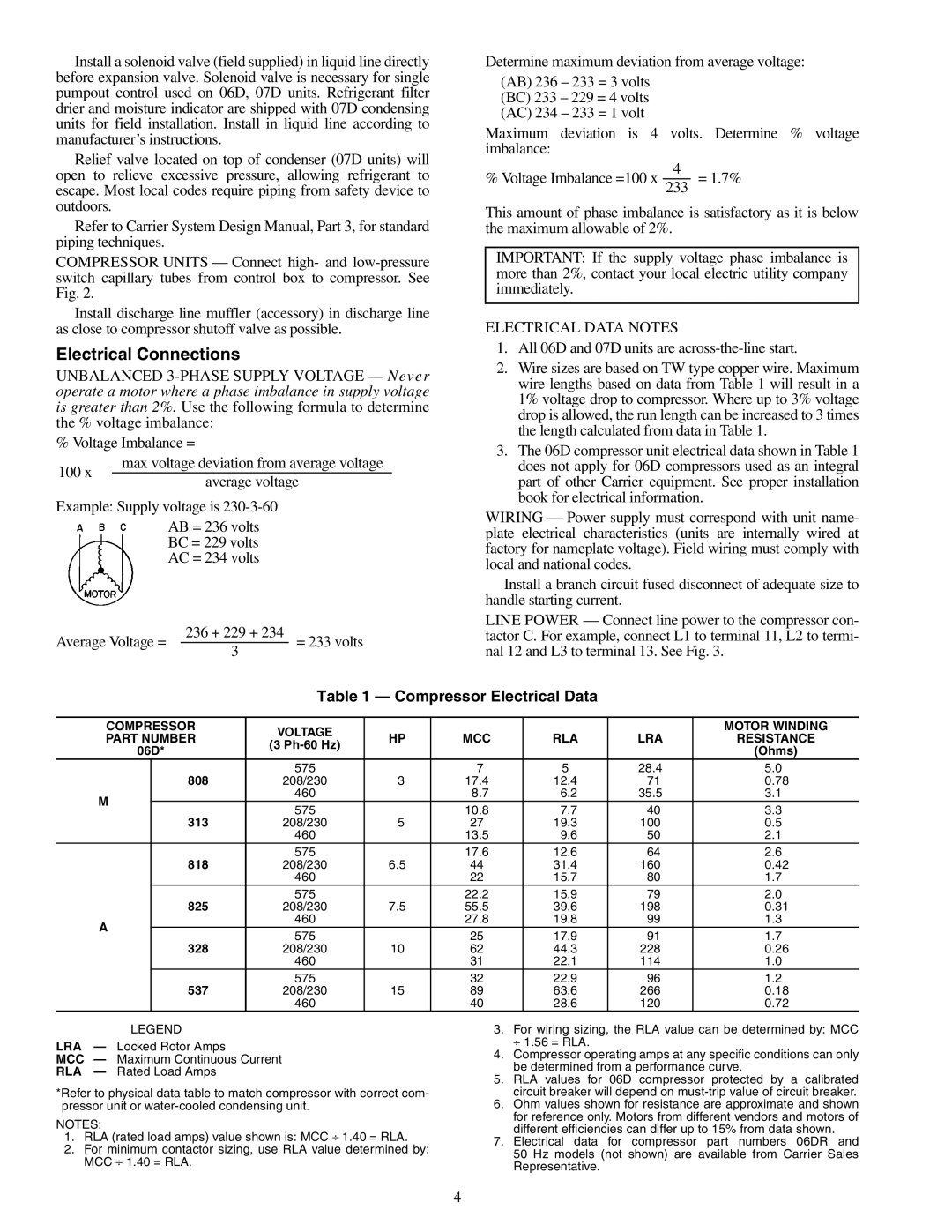
Example: Supply voltage is
AB = 236 volts
BC = 229 volts
AC = 234 volts
Average Voltage = | 236 + 229 + 234 | = 233 volts | |
3 | |||
|
|
Determine maximum deviation from average voltage:
(AB) 236 – 233 = 3 volts (BC) 233 – 229 = 4 volts (AC) 234 – 233 = 1 volt
Maximum deviation is 4 volts. Determine % voltage imbalance:
% Voltage Imbalance =100 x 2334 = 1.7%
This amount of phase imbalance is satisfactory as it is below the maximum allowable of 2%.
IMPORTANT: If the supply voltage phase imbalance is more than 2%, contact your local electric utility company immediately.
ELECTRICAL DATA NOTES
1.All 06D and 07D units are across-the-line start.
2.Wire sizes are based on TW type copper wire. Maximum wire lengths based on data from Table 1 will result in a 1% voltage drop to compressor. Where up to 3% voltage drop is allowed, the run length can be increased to 3 times the length calculated from data in Table 1.
3.The 06D compressor unit electrical data shown in Table 1 does not apply for 06D compressors used as an integral part of other Carrier equipment. See proper installation book for electrical information.
WIRING — Power supply must correspond with unit name- plate electrical characteristics (units are internally wired at factory for nameplate voltage). Field wiring must comply with local and national codes.
Install a branch circuit fused disconnect of adequate size to handle starting current.
LINE POWER — Connect line power to the compressor con- tactor C. For example, connect L1 to terminal 11, L2 to termi- nal 12 and L3 to terminal 13. See Fig. 3.
Table 1 — Compressor Electrical Data
COMPRESSOR | VOLTAGE |
|
|
|
| MOTOR WINDING | ||
PART NUMBER | HP | MCC | RLA | LRA | RESISTANCE | |||
(3 | ||||||||
06D* |
|
|
|
| (Ohms) | |||
|
|
|
|
| ||||
| 808 | 575 |
| 7 | 5 | 28.4 | 5.0 | |
| 208/230 | 3 | 17.4 | 12.4 | 71 | 0.78 | ||
M |
| 460 |
| 8.7 | 6.2 | 35.5 | 3.1 | |
313 | 575 |
| 10.8 | 7.7 | 40 | 3.3 | ||
|
| |||||||
| 208/230 | 5 | 27 | 19.3 | 100 | 0.5 | ||
|
| 460 |
| 13.5 | 9.6 | 50 | 2.1 | |
| 818 | 575 |
| 17.6 | 12.6 | 64 | 2.6 | |
| 208/230 | 6.5 | 44 | 31.4 | 160 | 0.42 | ||
|
| 460 |
| 22 | 15.7 | 80 | 1.7 | |
| 825 | 575 |
| 22.2 | 15.9 | 79 | 2.0 | |
| 208/230 | 7.5 | 55.5 | 39.6 | 198 | 0.31 | ||
A |
| 460 |
| 27.8 | 19.8 | 99 | 1.3 | |
328 | 575 |
| 25 | 17.9 | 91 | 1.7 | ||
|
| |||||||
| 208/230 | 10 | 62 | 44.3 | 228 | 0.26 | ||
|
| 460 |
| 31 | 22.1 | 114 | 1.0 | |
| 537 | 575 |
| 32 | 22.9 | 96 | 1.2 | |
| 208/230 | 15 | 89 | 63.6 | 266 | 0.18 | ||
|
| 460 |
| 40 | 28.6 | 120 | 0.72 | |
LEGEND
LRA — Locked Rotor Amps
MCC — Maximum Continuous Current
RLA — Rated Load Amps
*Refer to physical data table to match compressor with correct com- pressor unit or
NOTES:
1.RLA (rated load amps) value shown is: MCC ⎟ 1.40 = RLA.
2.For minimum contactor sizing, use RLA value determined by: MCC ⎟ 1.40 = RLA.
3.For wiring sizing, the RLA value can be determined by: MCC ⎟ 1.56 = RLA.
4.Compressor operating amps at any specific conditions can only be determined from a performance curve.
5.RLA values for 06D compressor protected by a calibrated circuit breaker will depend on
6.Ohm values shown for resistance are approximate and shown for reference only. Motors from different vendors and motors of different efficiencies can differ up to 15% from data shown.
7.Electrical data for compressor part numbers 06DR and 50 Hz models (not shown) are available from Carrier Sales Representative.
4