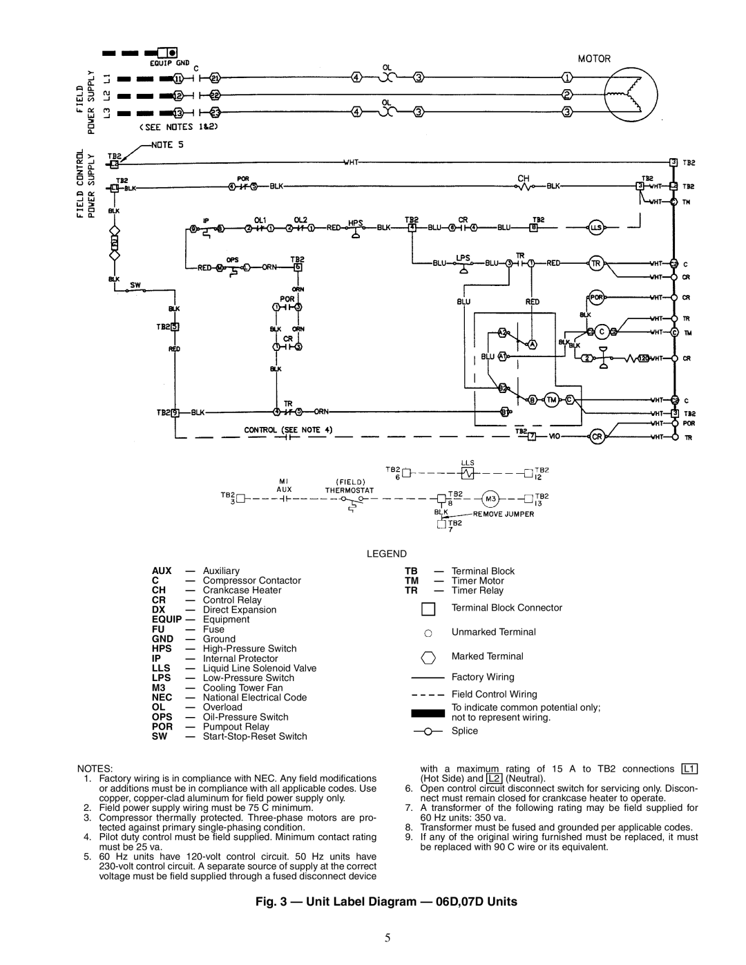
LEGEND
AUX — Auxiliary
C— Compressor Contactor CH — Crankcase Heater CR — Control Relay
DX | — | Direct Expansion |
EQUIP — | Equipment | |
FU | — | Fuse |
GND | — | Ground |
HPS | — | |
IP | — | Internal Protector |
LLS | — | Liquid Line Solenoid Valve |
LPS | — | |
M3 | — | Cooling Tower Fan |
NEC | — | National Electrical Code |
OL | — | Overload |
OPS | — | |
POR | — | Pumpout Relay |
SW | — |
|
NOTES:
1.Factory wiring is in compliance with NEC. Any field modifications or additions must be in compliance with all applicable codes. Use copper,
2.Field power supply wiring must be 75 C minimum.
3.Compressor thermally protected.
4.Pilot duty control must be field supplied. Minimum contact rating must be 25 va.
5.60 Hz units have
TB — Terminal Block
TM — Timer Motor
TR — Timer Relay
Terminal Block Connector
Unmarked Terminal
Marked Terminal
Factory Wiring
Field Control Wiring
To indicate common potential only; not to represent wiring.
Splice
with a maximum rating of 15 A to TB2 connections L1 (Hot Side) and L2 (Neutral).
6.Open control circuit disconnect switch for servicing only. Discon- nect must remain closed for crankcase heater to operate.
7.A transformer of the following rating may be field supplied for 60 Hz units: 350 va.
8.Transformer must be fused and grounded per applicable codes.
9.If any of the original wiring furnished must be replaced, it must be replaced with 90 C wire or its equivalent.
Fig. 3 — Unit Label Diagram — 06D,07D Units
5