Compressor Unit Connections — Extend power leads from control center (contactor terminals) to compressor terminal box and make connections as shown in Fig. 4.
Terminals 8 and 9 on motor terminal plate are for internal protector connections. As shown in Fig. 4, run a wire from ter- minal 9 to terminal 6 on TB2 in control center and a wire from terminal 1 on OL2 to terminal 2 on HPS in control center.
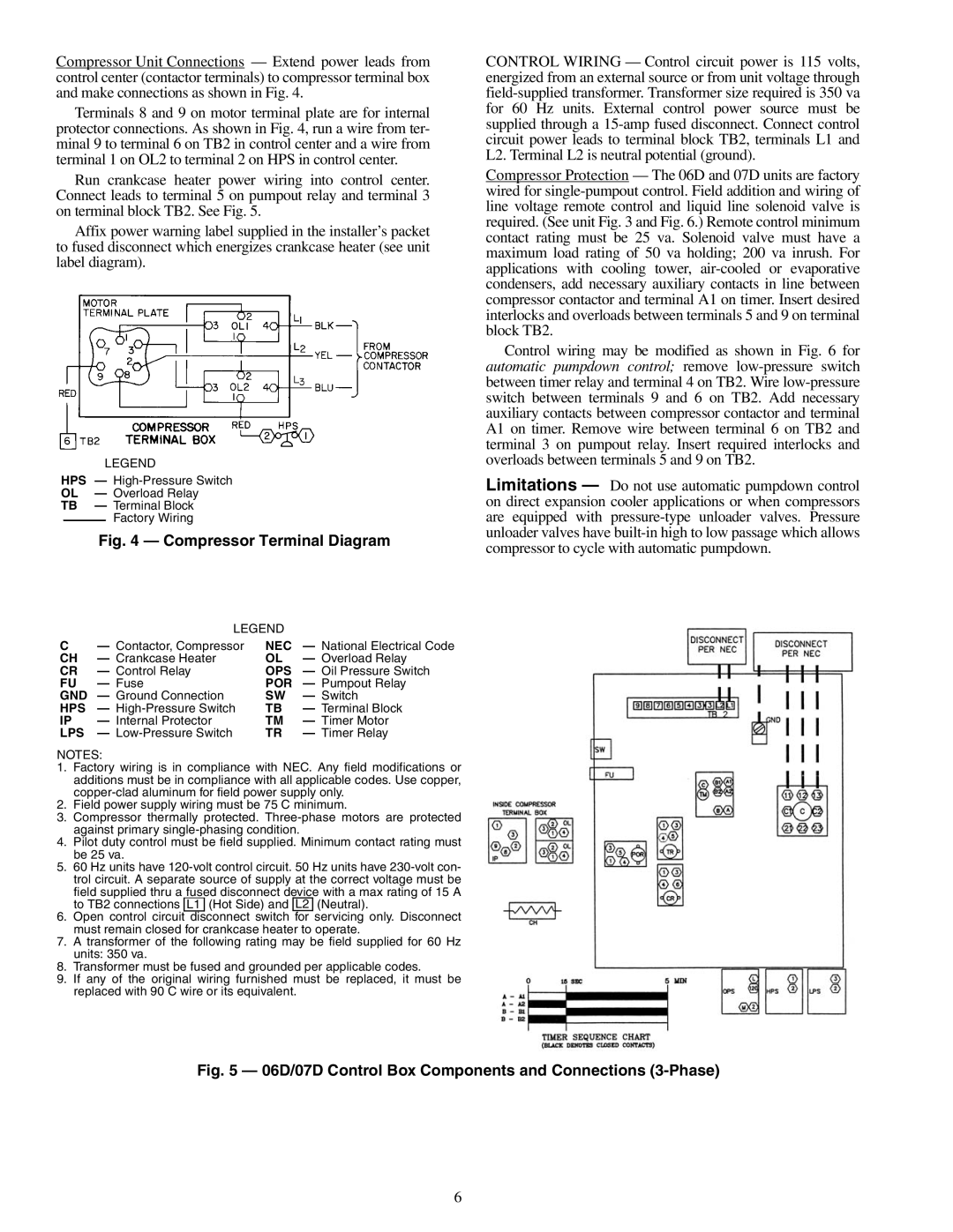
Run crankcase heater power wiring into control center. Connect leads to terminal 5 on pumpout relay and terminal 3 on terminal block TB2. See Fig. 5.
Affix power warning label supplied in the installer’s packet to fused disconnect which energizes crankcase heater (see unit label diagram).
LEGEND
HPS —
OL — Overload Relay
TB — Terminal Block
Factory Wiring
Fig. 4 — Compressor Terminal Diagram
LEGEND
C— Contactor, Compressor NEC — National Electrical Code
CH | — Crankcase Heater | OL | — Overload Relay |
CR | — Control Relay | OPS | — Oil Pressure Switch |
FU | — Fuse | POR | — Pumpout Relay |
GND | — Ground Connection | SW | — Switch |
HPS | — | TB | — Terminal Block |
IP | — Internal Protector | TM | — Timer Motor |
LPS | — | TR | — Timer Relay |
NOTES:
1.Factory wiring is in compliance with NEC. Any field modifications or additions must be in compliance with all applicable codes. Use copper,
2.Field power supply wiring must be 75 C minimum.
3.Compressor thermally protected.
4.Pilot duty control must be field supplied. Minimum contact rating must be 25 va.
5.60 Hz units have
6.Open control circuit disconnect switch for servicing only. Disconnect must remain closed for crankcase heater to operate.
7.A transformer of the following rating may be field supplied for 60 Hz units: 350 va.
8.Transformer must be fused and grounded per applicable codes.
9.If any of the original wiring furnished must be replaced, it must be replaced with 90 C wire or its equivalent.
CONTROL WIRING — Control circuit power is 115 volts, energized from an external source or from unit voltage through
Compressor Protection — The 06D and 07D units are factory wired for
Control wiring may be modified as shown in Fig. 6 for automatic pumpdown control; remove
Limitations — Do not use automatic pumpdown control on direct expansion cooler applications or when compressors are equipped with
Fig. 5 — 06D/07D Control Box Components and Connections (3-Phase)
6