LEGEND FOR FIG. 12
1 | — Motor Cover Gasket | 17 | — Oil Drain Plug | 34 | — Oil Ring |
2 | — Motor End Cover | 18 | — Crankcase | 35 | — Compression Rings |
3 | — Discharge Manifold Connection | 19 | — Bottom Plate Gasket | 36 | — Eccentric Strap |
4 | — Valve Plate Gasket | 20 | — Bottom Plate | 37 | — Eccentric Strap Side Shield |
5 | — Valve Plate Assembly | 21 | — Bottom Plate Washer and Cap Screw | 38 | — Pump End Counterweight |
6 | — Cylinder Head Gasket | 22 | — Oil Filter Screen | 39 | — Oil Pump Drive Segment |
7 | — Cylinder Head | 23 | — Oil Return Check Valve | 40 | — Drive Segment Cap Screws |
8 | — Cylinder Head Washer | 24 | — Oil Level Sight Glass |
| and Lockwashers |
| and Cap Screw | 25 | — Motor Terminal Plate | 41 | — Oil Feed Guide |
9 | — Suction Manifold Connection* | 26 | — Dowel Pins (For Suction Valve | 42 | — Oil Feed Guide Retainer Spring |
10 | — Suction Valve Positioning Spring |
| Positioning) | 43 | — Cover Gasket |
11 | — Suction Strainer | 27 | — Equalizing Tube and Lock Screw Assembly | 44 | — Pump Cover Cap Screw and Washer |
12 | — Bearing Head Gasket | 28 | — Lockwasher | 45 | — Counterweight Bolt |
13 | — Oil Pump Inlet Passage | 29 | — Rotor Lockwasher | 46 | — Eccentric Strap Side Shield |
14 | — Bearing Head Washer | 30 | — Rotor Drive Key | 47 | — Motor End Counterweight |
| and Cap Screw | 31 | — Piston Pin Lock Ring | 48 | — Locknut |
15 | — Oil Pump Cover | 32 | — Piston Pin | 49 | — Eccentric Shaft (or Crankshaft) |
16 | — Pump End Bearing Head | 33 | — Piston | *Used to add compressor oil. | |
|
|
|
| ||
1
2
3
4
5
8 ![]()
6
![]()
![]() 7
7
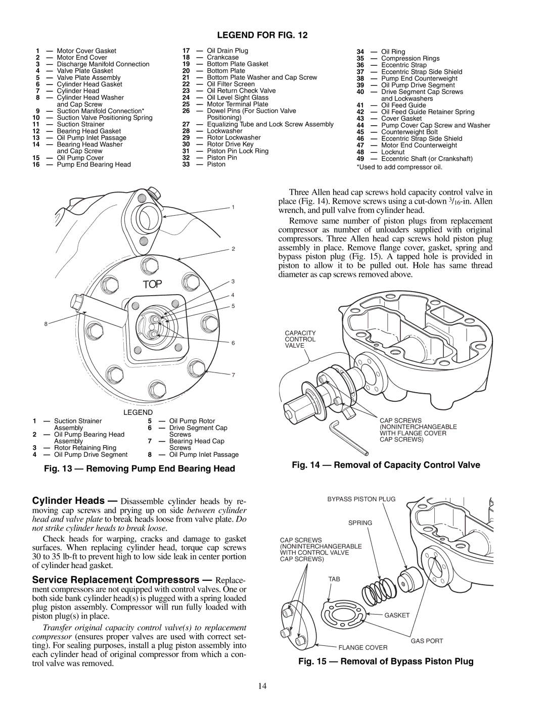
LEGEND
1 | — Suction Strainer | 5 | — Oil Pump Rotor |
| Assembly | 6 | — Drive Segment Cap |
2 | — Oil Pump Bearing Head |
| Screws |
| Assembly | 7 | — Bearing Head Cap |
3 | — Rotor Retaining Ring |
| Screws |
4 | — Oil Pump Drive Segment | 8 | — Oil Pump Inlet Passage |
Three Allen head cap screws hold capacity control valve in place (Fig. 14). Remove screws using a
Remove same number of piston plugs from replacement compressor as number of unloaders supplied with original compressors. Three Allen head cap screws hold piston plug assembly in place. Remove flange cover, gasket, spring and bypass piston plug (Fig. 15). A tapped hole is provided in piston to allow it to be pulled out. Hole has same thread diameter as cap screws removed above.
CAPACITY
CONTROL
VALVE
CAP SCREWS (NONINTERCHANGEABLE WITH FLANGE COVER CAP SCREWS)
Fig. 13 — Removing Pump End Bearing Head
Cylinder Heads — Disassemble cylinder heads by re- moving cap screws and prying up on side between cylinder head and valve plate to break heads loose from valve plate. Do not strike cylinder heads to break loose.
Check heads for warping, cracks and damage to gasket surfaces. When replacing cylinder head, torque cap screws 30 to 35
Service Replacement Compressors — Replace- ment compressors are not equipped with control valves. One or both side bank cylinder head(s) is plugged with a spring loaded plug piston assembly. Compressor will run fully loaded with piston plug(s) in place.
Transfer original capacity control valve(s) to replacement compressor (ensures proper valves are used with correct set- ting). For sealing purposes, install a plug piston assembly into each cylinder head of original compressor from which a con- trol valve was removed.
Fig. 14 — Removal of Capacity Control Valve
BYPASS PISTON PLUG
SPRING
CAP SCREWS (NONINTERCHANGERABLE WITH CONTROL VALVE CAP SCREWS)
TAB
![]() GASKET
GASKET
GAS PORT
![]() FLANGE COVER
FLANGE COVER
Fig. 15 — Removal of Bypass Piston Plug
14