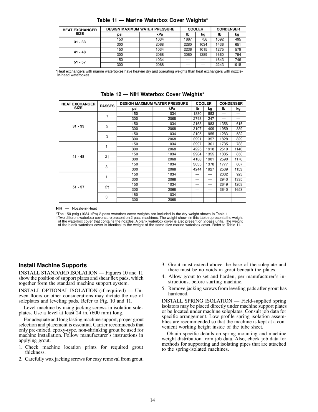
Table 11 Ð Marine Waterbox Cover Weights*
HEAT EXCHANGER | DESIGN MAXIMUM WATER PRESSURE | COOLER | CONDENSER | ||||
SIZE | psi | kPa | lb | kg | lb | kg | |
31 - 33 | 150 | 1034 | 1667 | 756 | 1092 | 495 | |
300 | 2068 | 2280 | 1034 | 1436 | 651 | ||
| |||||||
41 - 48 | 150 | 1034 | 2236 | 1015 | 1275 | 579 | |
300 | 2068 | 3060 | 1389 | 1660 | 754 | ||
| |||||||
51 - 57 | 150 | 1034 | Ð | Ð | 1643 | 746 | |
300 | 2068 | Ð | Ð | 2243 | 1018 | ||
| |||||||
|
|
|
|
|
|
| |
*Heat exchangers with marine waterboxes have heavier dry and operating weights than heat exchangers with nozzle-
Table 12 Ð NIH Waterbox Cover Weights*
HEAT EXCHANGER | PASSES | DESIGN MAXIMUM WATER PRESSURE | COOLER | CONDENSER | ||||
SIZE |
| psi | kPa | lb | kg | lb | kg | |
| 1 | 150 | 1034 | 1880 | 853 | Ð | Ð | |
| 300 | 2068 | 2748 | 1247 | Ð | Ð | ||
|
| |||||||
31 - 33 | 2 | 150 | 1034 | 2168 | 983 | 1356 | 615 | |
300 | 2068 | 3107 | 1409 | 1959 | 889 | |||
|
| |||||||
| 3 | 150 | 1034 | 2105 | 955 | 1283 | 582 | |
| 300 | 2068 | 2991 | 1357 | 1828 | 829 | ||
|
| |||||||
| 1 | 150 | 1034 | 2997 | 1361 | 1735 | 788 | |
| 300 | 2068 | 4225 | 1918 | 2510 | 1140 | ||
|
| |||||||
41 - 48 | 2² | 150 | 1034 | 2984 | 1355 | 1885 | 856 | |
300 | 2068 | 4188 | 1901 | 2590 | 1176 | |||
|
| |||||||
| 3 | 150 | 1034 | 3035 | 1378 | 1777 | 807 | |
| 300 | 2068 | 4244 | 1927 | 2539 | 1153 | ||
|
| |||||||
| 1 | 150 | 1034 | Ð | Ð | 2032 | 923 | |
| 300 | 2068 | Ð | Ð | 2940 | 1335 | ||
|
| |||||||
51 - 57 | 2² | 150 | 1034 | Ð | Ð | 2649 | 1203 | |
300 | 2068 | Ð | Ð | 3640 | 1653 | |||
|
| |||||||
| 3 | 150 | 1034 | Ð | Ð | Ð | Ð | |
| 300 | 2068 | Ð | Ð | Ð | Ð | ||
|
| |||||||
|
|
|
|
|
|
|
| |
NIH Ð
*The 150 psig (1034 kPa)
²Two different waterbox covers are present on
Install Machine Supports
INSTALL STANDARD ISOLATION Ð Figures 10 and 11 show the position of support plates and shear ¯ex pads, which together form the standard machine support system.
INSTALL OPTIONAL ISOLATION (if required) Ð Un- even ¯oors or other considerations may dictate the use of soleplates and leveling pads. Refer to Fig. 10 and 11.
Level machine by using jacking screws in isolation sole- plates. Use a level at least 24 in. (600 mm) long.
For adequate and long lasting machine support, proper grout selection and placement is essential. Carrier recommends that only
1.Check machine location prints for required grout thickness.
2.Carefully wax jacking screws for easy removal from grout.
3.Grout must extend above the base of the soleplate and there must be no voids in grout beneath the plates.
4.Allow grout to set and harden, per manufacturer's in- structions, before starting machine.
5.Remove jacking screws from leveling pads after grout has hardened.
INSTALL SPRING ISOLATION Ð
Obtain speci®c details on spring mounting and machine weight distribution from job data. Also, check job data for methods for supporting and isolating pipes that are attached to the
14
