Install Field Insulation
Protect insulation from weld heat damage and weld splat- ter. Cover with wet canvas cover during water piping installation.
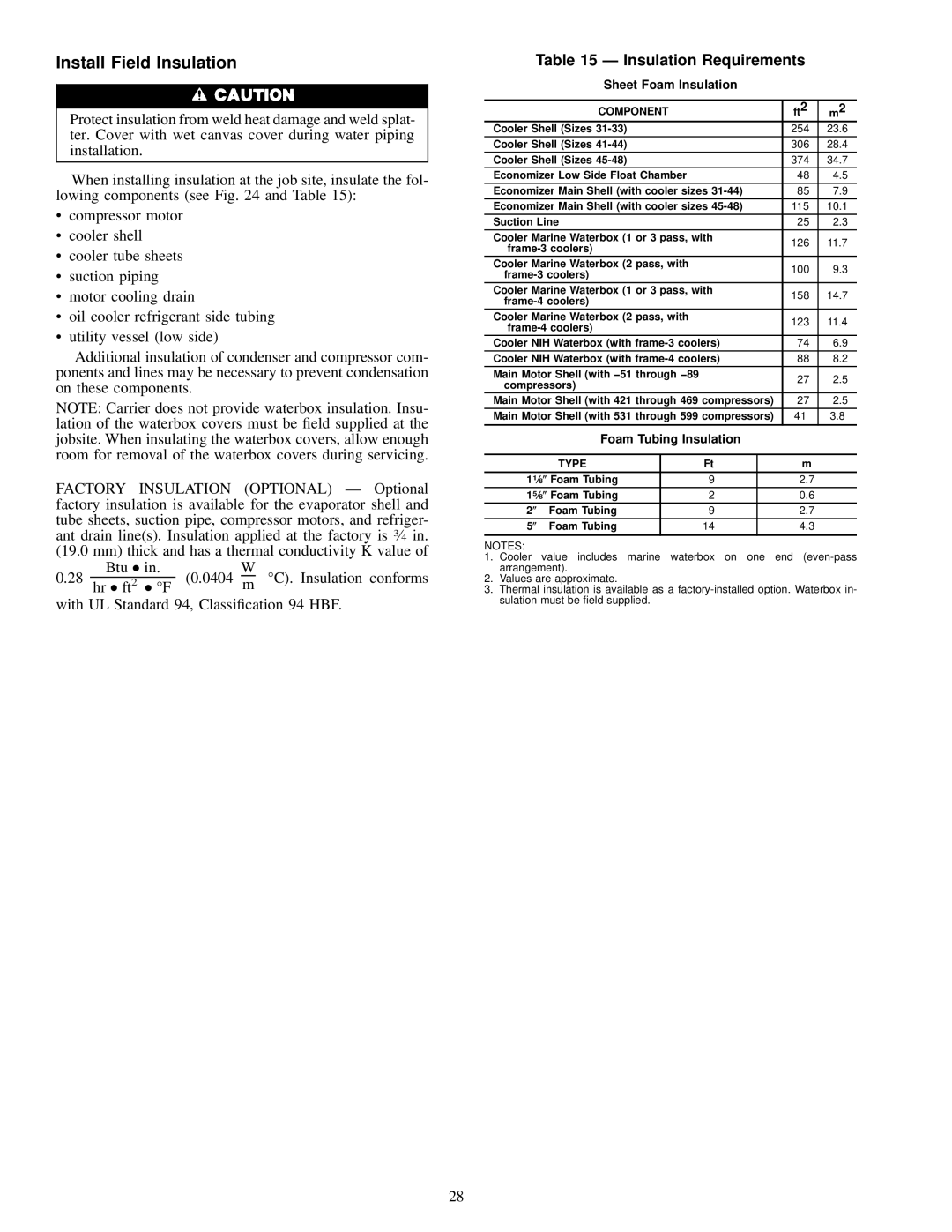
When installing insulation at the job site, insulate the fol- lowing components (see Fig. 24 and Table 15):
·compressor motor
·cooler shell
·cooler tube sheets
·suction piping
·motor cooling drain
·oil cooler refrigerant side tubing
·utility vessel (low side)
Additional insulation of condenser and compressor com- ponents and lines may be necessary to prevent condensation on these components.
NOTE: Carrier does not provide waterbox insulation. Insu- lation of the waterbox covers must be ®eld supplied at the jobsite. When insulating the waterbox covers, allow enough room for removal of the waterbox covers during servicing.
FACTORY INSULATION (OPTIONAL) Ð Optional factory insulation is available for the evaporator shell and tube sheets, suction pipe, compressor motors, and refriger- ant drain line(s). Insulation applied at the factory is 3¤4 in. (19.0 mm) thick and has a thermal conductivity K value of
0.28 | Btu | in. | (0.0404 | W | °C). Insulation conforms |
hr ft2 | °F | m |
with UL Standard 94, Classi®cation 94 HBF.
Table 15 Ð Insulation Requirements
Sheet Foam Insulation
|
| COMPONENT |
|
| ft2 | m2 | |
| Cooler Shell (Sizes |
|
| 254 | 23.6 | ||
| Cooler Shell (Sizes |
|
| 306 | 28.4 | ||
| Cooler Shell (Sizes |
|
| 374 | 34.7 | ||
| Economizer Low Side Float Chamber |
|
| 48 | 4.5 | ||
| Economizer Main Shell (with cooler sizes | 85 | 7.9 | ||||
| Economizer Main Shell (with cooler sizes | 115 | 10.1 | ||||
| Suction Line |
|
| 25 | 2.3 | ||
| Cooler Marine Waterbox (1 or 3 pass, with | 126 | 11.7 | ||||
|
|
| |||||
|
|
|
|
| |||
| Cooler Marine Waterbox (2 pass, with |
|
| 100 | 9.3 | ||
|
|
| |||||
|
|
|
|
| |||
| Cooler Marine Waterbox (1 or 3 pass, with | 158 | 14.7 | ||||
|
|
| |||||
|
|
|
|
| |||
| Cooler Marine Waterbox (2 pass, with |
|
| 123 | 11.4 | ||
|
|
| |||||
|
|
|
|
| |||
| Cooler NIH Waterbox (with | 74 | 6.9 | ||||
| Cooler NIH Waterbox (with | 88 | 8.2 | ||||
| Main Motor Shell (with −51 through −89 |
|
| 27 | 2.5 | ||
| compressors) |
|
| ||||
|
|
|
|
| |||
| Main Motor Shell (with 421 through 469 compressors) | 27 | 2.5 | ||||
| Main Motor Shell (with 531 through 599 compressors) | 41 | 3.8 | ||||
|
|
|
|
|
|
| |
|
| Foam Tubing Insulation |
|
| |||
|
|
|
|
|
|
|
|
|
| TYPE |
| Ft |
| m |
|
| 11¤8 | Foam Tubing |
| 9 |
| 2.7 |
|
| 15¤8 | Foam Tubing |
| 2 |
| 0.6 |
|
| 2 | Foam Tubing |
| 9 |
| 2.7 |
|
5 | Foam Tubing |
| 14 |
| 4.3 |
| |
|
|
|
|
|
|
|
|
NOTES:
1.Cooler value includes marine waterbox on one end
2.Values are approximate.
3.Thermal insulation is available as a
28
