Insulate Motor Terminals and Lead Wire Ends Ð Insulate compressor motor terminals, lead wire ends, and electrical wires to prevent moisture condensation and electrical arc- ing. For
1.Insulate each terminal by wrapping with one layer of insulation putty.
2.Overwrap putty with 4 layers of vinyl tape.
Connect Power Wires to Oil Pump Contactor Ð Connect power wires to oil pump contactor mounted in machine power panel. (See Fig. 19.) Use the electrical disconnect located in the machine starter (if supplied), or a separate fused disconnect as shown on job wiring diagrams. Check that power supply voltage agrees with oil pump voltage. Follow correct phas- ing for proper motor rotation.
Do not wire into the top surface of the power panel. Knock- outs are provided on the underside of the panel.
Connect Power Wires to Oil Heater Contactor Ð Connect control power wiring between the oil heater contactor ter- minals (Fig. 17 and 18) and terminals LL1 and LL2 on the ®eld wiring strip in the compressor motor starter. Refer to Fig. 21 and wiring label on the chiller power panel.
Voltage to terminals LL1 and LL2 comes from a con- trol transformer in a starter built to Carrier speci®ca- tions. Do not connect an outside source of control power to the compressor motor starter (terminals LL1 and LL2). An outside power source will produce dangerous volt- age at the line side of the starter, because supplying volt- age at the transformer secondary terminals produces in- put level voltage at the transformer primary terminals.
Connect Communication and Control Wiring from Starter to Power Panel Ð Connect control wiring from main motor starter to the chiller power panel. All control wiring must use shielded cable. Also connect the communications cable. Make sure the control circuit is grounded in accordance with applicable electrical codes and instructions on chiller control wiring label.
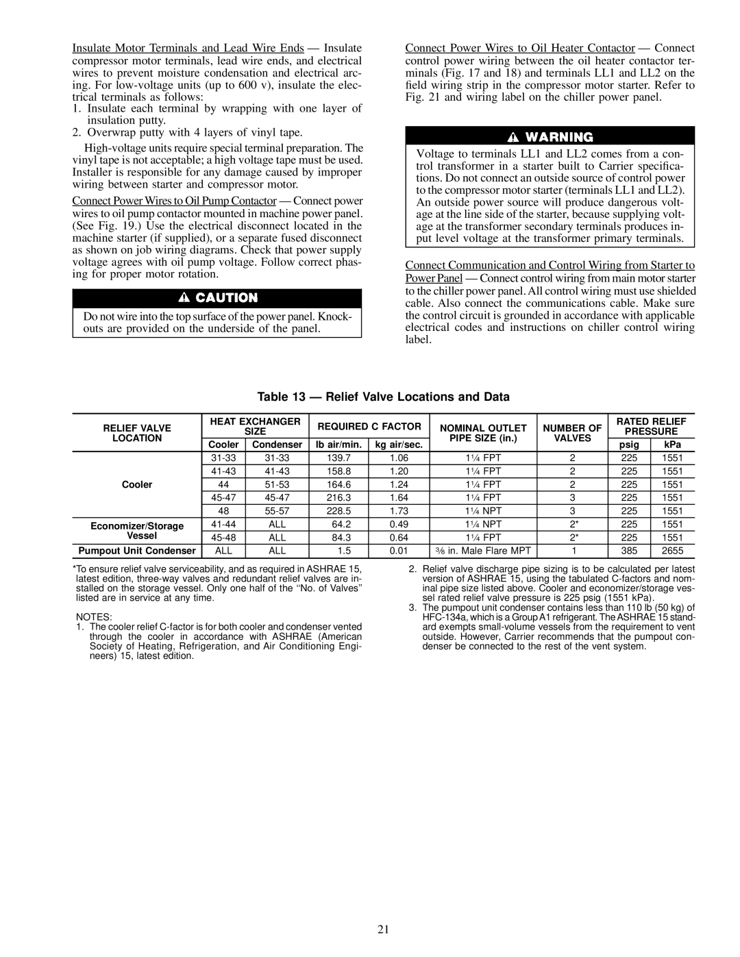
Table 13 Ð Relief Valve Locations and Data
RELIEF VALVE | HEAT EXCHANGER | REQUIRED C FACTOR | NOMINAL OUTLET | NUMBER OF | RATED RELIEF | ||||
| SIZE | PRESSURE | |||||||
LOCATION |
|
|
| PIPE SIZE (in.) | VALVES | ||||
Cooler | Condenser | lb air/min. | kg air/sec. | psig | kPa | ||||
|
|
| |||||||
| 139.7 | 1.06 | 11¤4 FPT | 2 | 225 | 1551 | |||
| 158.8 | 1.20 | 11¤4 FPT | 2 | 225 | 1551 | |||
Cooler | 44 | 164.6 | 1.24 | 11¤4 FPT | 2 | 225 | 1551 | ||
| 216.3 | 1.64 | 11¤4 FPT | 3 | 225 | 1551 | |||
| 48 | 228.5 | 1.73 | 11¤4 NPT | 3 | 225 | 1551 | ||
Economizer/Storage | ALL | 64.2 | 0.49 | 11¤4 NPT | 2* | 225 | 1551 | ||
Vessel | ALL | 84.3 | 0.64 | 11¤4 FPT | 2* | 225 | 1551 | ||
Pumpout Unit Condenser | ALL | ALL | 1.5 | 0.01 | 3¤8 in. Male Flare MPT | 1 | 385 | 2655 | |
*To ensure relief valve serviceability, and as required in ASHRAE 15, latest edition,
NOTES:
1.The cooler relief
2.Relief valve discharge pipe sizing is to be calculated per latest version of ASHRAE 15, using the tabulated
3.The pumpout unit condenser contains less than 110 lb (50 kg) of
21