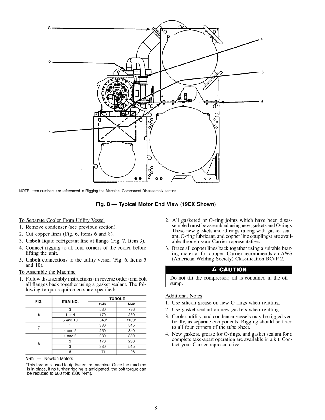
NOTE: Item numbers are referenced in Rigging the Machine, Component Disassembly section.
Fig. 8 Ð Typical Motor End View (19EX Shown)
To Separate Cooler From Utility Vessel
1.Remove condenser (see previous section).
2.Cut copper lines (Fig. 6, Items 6 and 8).
3.Unbolt liquid refrigerant line at ¯ange (Fig. 7, Item 3).
4.Connect rigging to all four corners of the cooler before lifting the unit.
5.Unbolt connections to the utility vessel (Fig. 6, Items 5 and 10).
To Assemble the Machine
1.Follow disassembly instructions (in reverse order) and bolt all ¯anges back together using a gasket sealant. The fol- lowing torque requirements are speci®ed:
2.All gasketed or
3.Braze all copper lines back together using a suitable braz- ing material for copper. Carrier recommends an AWS (American Welding Society) Classi®cation
Do not tilt the compressor; oil is contained in the oil sump.
FIG. | ITEM NO. |
| TORQUE | |
|
| |||
|
|
| ||
| 3 | 580 |
| 786 |
6 | 1 or 4 | 170 |
| 230 |
| 5 and 10 | 840* |
| 1139* |
7 | 1 | 380 |
| 515 |
4 and 5 | 250 |
| 340 | |
|
| |||
| 1 and 6 | 280 |
| 380 |
8 | 2 | 170 |
| 230 |
3 | 380 |
| 515 | |
|
| |||
| 5 | 71 |
| 96 |
|
|
|
|
|
Additional Notes
1.Use silicon grease on new
2.Use gasket sealant on new gaskets when re®tting.
3.Cooler, utility, and condenser vessels may be rigged ver- tically, as separate components. Rigging should be ®xed to all four corners of the tube sheet.
4.New gaskets, grease for
*This torque is used to rig the entire machine. Once the machine is in place, if no further rigging is anticipated, the bolt torque can be reduced to 280
8
