Connect Piping
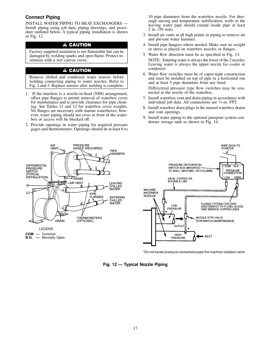
INSTALL WATER PIPING TO HEAT EXCHANGERS Ð Install piping using job data, piping drawings, and proce- dure outlined below. A typical piping installation is shown in Fig. 12.
Remove chilled and condenser water sensors before welding connecting piping to water nozzles. Refer to Fig. 2 and 3. Replace sensors after welding is complete.
1.If the machine is a
2.Provide openings in water piping for required pressure gages and thermometers. Openings should be at least 6 to
10 pipe diameters from the waterbox nozzle. For thor- ough mixing and temperature stabilization, wells in the leaving water pipe should extend inside pipe at least 2 in. (50 mm).
3.Install air vents at all high points in piping to remove air and prevent water hammer.
4.Install pipe hangers where needed. Make sure no weight or stress is placed on waterbox nozzles or ¯anges.
5.Water ¯ow direction must be as speci®ed in Fig. 13.
NOTE: Entering water is always the lower of the 2 nozzles. Leaving water is always the upper nozzle for cooler or condenser.
6.Water ¯ow switches must be of
Differential pressure type ¯ow switches may be con- nected at the nozzle of the waterbox.
7.Install waterbox vent and drain piping in accordance with individual job data. All connections are
8.Install waterbox drain plugs in the unused waterbox drains and vent openings.
9.Install water piping to the optional pumpout system con- denser storage tank as shown in Fig. 14.
LEGEND
COM Ð Common
N.O. Ð Normally Open
*Do not locate pressure connections past the machine isolation valve.
Fig. 12 Ð Typical Nozzle Piping
17