NOTES:
1.Certi®ed drawings available upon request.
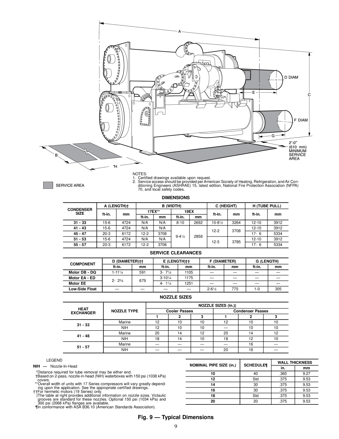
2.Service access should be provided per American Society of Heating, Refrigeration, and Air Con- ditioning Engineers (ASHRAE) 15, latest edition, National Fire Protection Association (NFPA) 70, and local safety codes.
DIMENSIONS
CONDENSER |
|
| A (LENGTH)² |
|
|
|
| B (WIDTH) |
|
|
| C (HEIGHT) |
|
| H (TUBE PULL) | |||||||||||||||
|
|
|
|
|
|
|
| 17EX** |
| 19EX |
|
|
|
|
|
|
|
|
|
|
|
|
|
| ||||||
SIZE |
|
| mm |
|
|
|
|
|
|
|
| mm |
|
|
|
| mm | |||||||||||||
|
|
|
| mm |
|
| mm |
|
|
|
|
|
|
| ||||||||||||||||
|
|
|
|
|
|
|
|
|
|
|
|
|
|
|
|
|
|
|
|
|
|
| ||||||||
31 - 33 |
| 4724 |
|
| N/A |
| N/A |
|
| 2692 |
|
| 3264 |
|
| 3912 | ||||||||||||||
41 - 43 |
| 4724 |
|
| N/A |
| N/A |
|
|
|
|
|
|
|
| 3708 |
|
| 3912 | |||||||||||
45 - 47 |
| 6172 |
|
|
| 3708 |
|
|
| 2858 |
|
|
| 17- 6 |
| 5334 | ||||||||||||||
|
|
|
|
|
|
|
|
|
|
|
|
|
|
| ||||||||||||||||
51 - 53 |
| 4724 |
|
| N/A |
| N/A |
|
|
|
| 3785 |
|
| 3912 | |||||||||||||||
|
|
|
|
|
|
|
|
|
|
|
|
|
| |||||||||||||||||
55 - 57 |
| 6172 |
|
|
| 3708 |
|
|
|
|
|
|
|
|
|
| 17- 6 |
| 5334 | |||||||||||
|
|
|
|
|
|
|
|
|
|
|
|
|
|
|
|
|
|
| ||||||||||||
|
|
|
|
|
|
|
|
|
|
|
|
|
|
|
|
|
|
|
|
|
|
|
|
|
|
|
|
|
| |
|
|
|
|
|
|
|
|
|
| SERVICE CLEARANCES |
|
|
|
|
|
|
|
|
|
|
|
| ||||||||
|
|
|
|
|
|
|
|
|
|
|
|
|
|
|
|
|
|
|
|
|
|
| ||||||||
COMPONENT |
|
|
| D (DIAMETER)²² |
| E (LENGTH)²² |
|
| F (DIAMETER) |
|
| G (LENGTH) | ||||||||||||||||||
|
|
|
|
| mm |
|
| mm |
|
|
|
| mm |
|
|
|
| mm | ||||||||||||
|
|
|
|
|
|
|
|
|
|
|
|
|
|
| ||||||||||||||||
Motor DB - DQ |
|
|
|
|
| 591 |
|
| 3- 71¤2 |
| 1105 |
|
| Ð |
|
| Ð |
|
| Ð |
| Ð | ||||||||
Motor EA - ED |
|
|
| 2- 23¤4 |
|
| 679 |
|
|
| 1175 |
|
| Ð |
|
| Ð |
|
| Ð |
| Ð | ||||||||
Motor EE |
|
|
|
|
|
|
| 4- 11¤4 |
| 1251 |
|
| Ð |
|
| Ð |
|
|
| Ð |
|
| Ð | |||||||
|
|
|
|
|
|
|
|
|
|
|
|
|
|
|
|
|
| |||||||||||||
|
|
| Ð |
|
| Ð |
|
| Ð |
|
| Ð |
|
|
| 1¤2 |
| 775 |
|
|
| 305 | ||||||||
|
|
|
|
|
|
|
|
|
|
| NOZZLE SIZES |
|
|
|
|
|
|
|
|
|
|
|
|
|
| |||||
|
|
|
|
|
|
|
|
|
|
|
|
|
|
|
|
|
|
|
|
|
|
|
|
|
| |||||
HEAT |
|
|
|
|
|
|
|
|
|
|
|
|
|
|
|
| NOZZLE SIZES (in.) |
|
|
|
|
|
| |||||||
|
|
| NOZZLE TYPE |
|
|
| Cooler Passes |
|
|
|
|
|
| Condenser Passes | ||||||||||||||||
EXCHANGER |
|
|
|
|
|
|
|
|
|
|
|
| ||||||||||||||||||
|
|
|
|
|
|
|
|
|
| 1 |
| 2 |
|
| 3 |
|
| 1 |
|
| 2 | 3 | ||||||||
31 - 33 |
|
|
|
| Marine |
|
| 12 |
| 10 |
|
| 10 |
|
| 12 |
| 10 | 10 | |||||||||||
|
|
|
| NIH |
|
| 12 |
| 10 |
|
| 10 |
|
| Ð |
|
| 10 | 10 | |||||||||||
|
|
|
|
|
|
|
|
|
|
|
|
|
| |||||||||||||||||
41 - 48 |
|
|
|
| Marine |
|
| 20 |
| 14 |
|
| 12 |
|
| 20 |
| 14 | 12 | |||||||||||
|
|
|
| NIH |
|
| 18 |
| 14 |
|
| 10 |
|
| 18 |
| 12 | 10 | ||||||||||||
|
|
|
|
|
|
|
|
|
|
|
|
| ||||||||||||||||||
51 - 57 |
|
|
|
| Marine |
|
| Ð |
| Ð |
|
| Ð |
|
| Ð |
|
|
|
| 16 | Ð | ||||||||
|
|
|
| NIH |
|
| Ð |
| Ð |
|
| Ð |
|
| 20 |
|
|
|
| 16 | Ð | |||||||||
|
|
|
|
|
|
|
|
|
|
|
|
|
|
|
| |||||||||||||||
LEGEND
NIH Ð
*Distance required for tube removal may be either end.
²Based on
**Overall width of units with 17 Series compressors will vary greatly depend- ing upon the application. See the appropriate certi®ed drawings.
²²For hermetic motors (19 Series) only.
The table at right provides additional information on nozzle sizes. Victaulic grooves are standard for these nozzles. Optional 150 psi (1034 kPa) and 300 psi (2068 kPa) ¯anges are available.
¶In conformance with ASA B36.10 (American Standards Association).
NOMINAL PIPE SIZE (in.) | SCHEDULE¶ | WALL THICKNESS | ||
in. | mm | |||
|
| |||
10 | 40 | .365 | 9.27 | |
12 | Std | .375 | 9.53 | |
14 | 30 | .375 | 9.53 | |
16 | 30 | .375 | 9.53 | |
18 | Std | .375 | 9.53 | |
20 | 20 | .375 | 9.53 | |
|
|
|
| |
Fig. 9 Ð Typical Dimensions
9