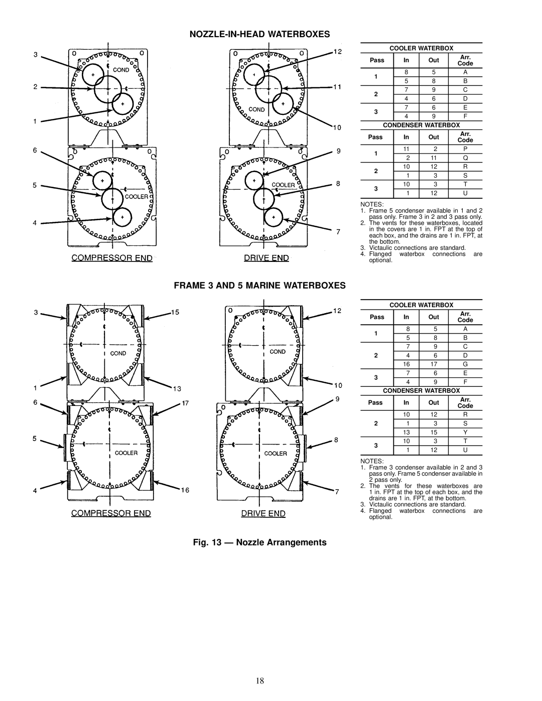
NOZZLE-IN-HEAD WATERBOXES
COOLER WATERBOX
Pass | In | Out | Arr. | |
Code | ||||
|
|
| ||
1 | 8 | 5 | A | |
5 | 8 | B | ||
| ||||
2 | 7 | 9 | C | |
4 | 6 | D | ||
| ||||
3 | 7 | 6 | E | |
4 | 9 | F | ||
| ||||
CONDENSER WATERBOX | ||||
Pass | In | Out | Arr. | |
Code | ||||
|
|
| ||
1 | 11 | 2 | P | |
2 | 11 | Q | ||
| ||||
2 | 10 | 12 | R | |
1 | 3 | S | ||
| ||||
3 | 10 | 3 | T | |
1 | 12 | U | ||
| ||||
|
|
|
| |
NOTES:
1. Frame 5 condenser available in 1 and 2 pass only. Frame 3 in 2 and 3 pass only.
2. The vents for these waterboxes, located in the covers are 1 in. FPT at the top of each box, and the drains are 1 in. FPT, at the bottom.
3. Victaulic connections are standard.
4. Flanged waterbox connections are optional.
FRAME 3 AND 5 MARINE WATERBOXES
COOLER WATERBOX
Pass | In | Out | Arr. | |
Code | ||||
|
|
| ||
1 | 8 | 5 | A | |
5 | 8 | B | ||
| ||||
| 7 | 9 | C | |
2 | 4 | 6 | D | |
| 16 | 17 | G | |
3 | 7 | 6 | E | |
4 | 9 | F | ||
| ||||
CONDENSER WATERBOX | ||||
Pass | In | Out | Arr. | |
Code | ||||
|
|
| ||
| 10 | 12 | R | |
2 | 1 | 3 | S | |
| 13 | 15 | Y | |
3 | 10 | 3 | T | |
1 | 12 | U | ||
| ||||
|
|
|
| |
NOTES:
1. Frame 3 condenser available in 2 and 3 pass only. Frame 5 condenser available in 2 pass only.
2. The vents for these waterboxes are 1 in. FPT at the top of each box, and the drains are 1 in. FPT, at the bottom.
3. Victaulic connections are standard.
4. Flanged waterbox connections are optional.
Fig. 13 Ð Nozzle Arrangements
18