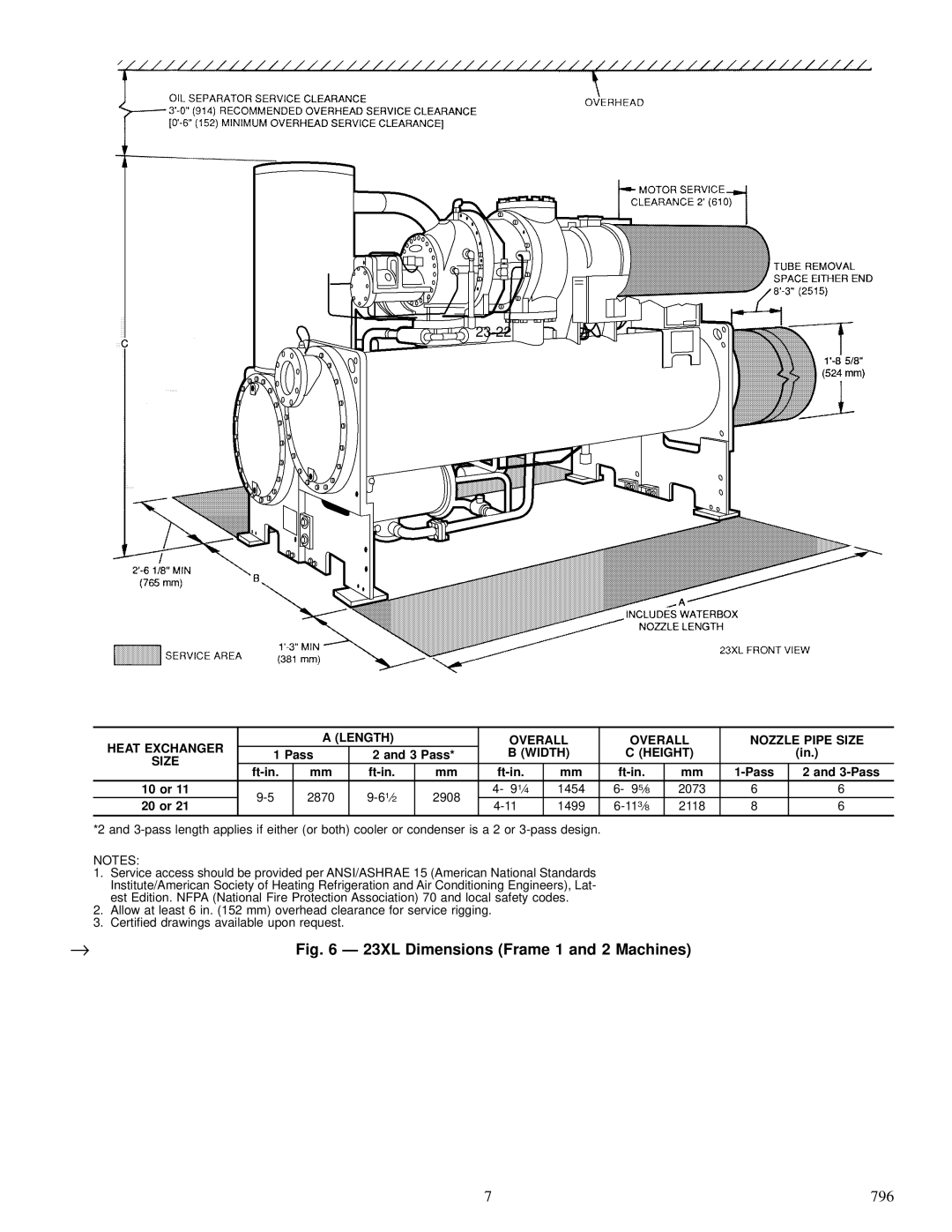
23 XL specifications
The Carrier 23 XL series is an advanced line of air conditioning units designed for optimal cooling performance and energy efficiency. This unit stands out in the HVAC industry due to its integration of cutting-edge technologies and user-friendly features.One of the main features of the Carrier 23 XL is its use of the Greenspeed Intelligence technology. This innovative system allows the unit to modulate its cooling output based on the actual needs of the environment, resulting in significant energy savings. By adjusting the compressor speed, the 23 XL can maintain a consistent temperature without the energy spikes common in traditional air conditioning systems.
Another notable characteristic of the Carrier 23 XL is its high SEER rating, which stands for Seasonal Energy Efficiency Ratio. The 23 XL boasts a SEER rating of up to 24, making it one of the most efficient units available on the market. This efficiency translates to lower utility bills and a reduced carbon footprint, which is a crucial consideration in today’s sustainability-focused world.
The Carrier 23 XL is also equipped with a variable-speed compressor, which enhances its overall performance. This component allows for quieter operation, providing comfortable indoor conditions without noise disturbances. Homeowners can enjoy peace and quiet while the system operates seamlessly in the background.
Moreover, the Carrier 23 XL features advanced air filtration capabilities. The unit is designed with high-efficiency filters that capture dust, pollen, and other airborne particles, improving indoor air quality. This feature is particularly beneficial for individuals with allergies or respiratory conditions, as it ensures a healthier living environment.
The sleek and compact design of the Carrier 23 XL makes it suitable for various installation configurations, maintaining aesthetic appeal without sacrificing performance. Additionally, it offers a range of smart features, such as compatibility with Wi-Fi-enabled thermostats, allowing users to control their home environment remotely via smartphone applications.
Finally, Carrier’s commitment to quality and reliability is evident in the 23 XL model. With robust construction and a warranty that provides peace of mind, homeowners can trust that their investment will deliver comfort and efficiency for years to come. Overall, the Carrier 23 XL is an exceptional choice for those seeking a blend of advanced technology, energy efficiency, and superior indoor comfort.

