Typical control wiring schematics
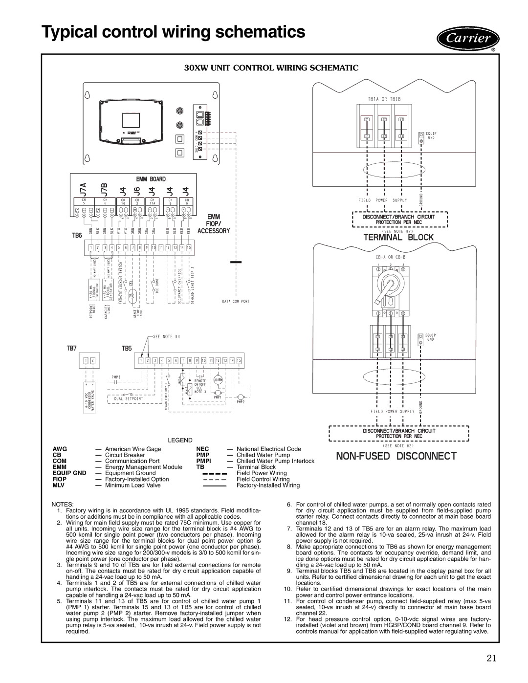
30XW UNIT CONTROL WIRING SCHEMATIC
a30-4697
| LEGEND |
|
|
AWG | — American Wire Gage | NEC | — National Electrical Code |
CB | — Circuit Breaker | PMP | — Chilled Water Pump |
COM | — Communication Port | PMPI | — Chilled Water Pump Interlock |
EMM | — Energy Management Module | TB | — Terminal Block |
EQUIP GND | — Equipment Ground |
| Field Power Wiring |
FIOP | — |
| Field Control Wiring |
MLV | — Minimum Load Valve |
|
|
NOTES:
1.Factory wiring is in accordance with UL 1995 standards. Field modifica- tions or additions must be in compliance with all applicable codes.
2.Wiring for main field supply must be rated 75C minimum. Use copper for all units. Incoming wire size range for the terminal block is #4 AWG to 500 kcmil for single point power (two conductors per phase). Incoming wire size range for the terminal blocks for dual point power option is #4 AWG to 500 kcmil for single point power (one conductor per phase). Incoming wire size range for
3.Terminals 9 and 10 of TB5 are for field external connections for remote
4.Terminals 1 and 2 of TB5 are for external connections of chilled water pump interlock. The contacts must be rated for dry circuit application capable of handling a
5.Terminals 11 and 13 of TB5 are for control of chilled water pump 1 (PMP 1) starter. Terminals 15 and 13 of TB5 are for control of chilled water pump 2 (PMP 2) starter. Remove
6.For control of chilled water pumps, a set of normally open contacts rated for dry circuit application must be supplied from
7.Terminals 12 and 13 of TB5 are for an alarm relay. The maximum load allowed for the alarm relay is
8.Make appropriate connections to TB6 as shown for energy management board options. The contacts for occupancy override, demand limit, and ice done options must be rated for dry circuit application capable for han- dling a
9.Terminal blocks TB5 and TB6 are located in the display panel box for all units. Refer to certified dimensional drawing for each unit to get the exact locations.
10.Refer to certified dimensional drawings for exact locations of the main power and control power entrance locations.
11.For control of condenser pump, connect
12.For head pressure control option,
21