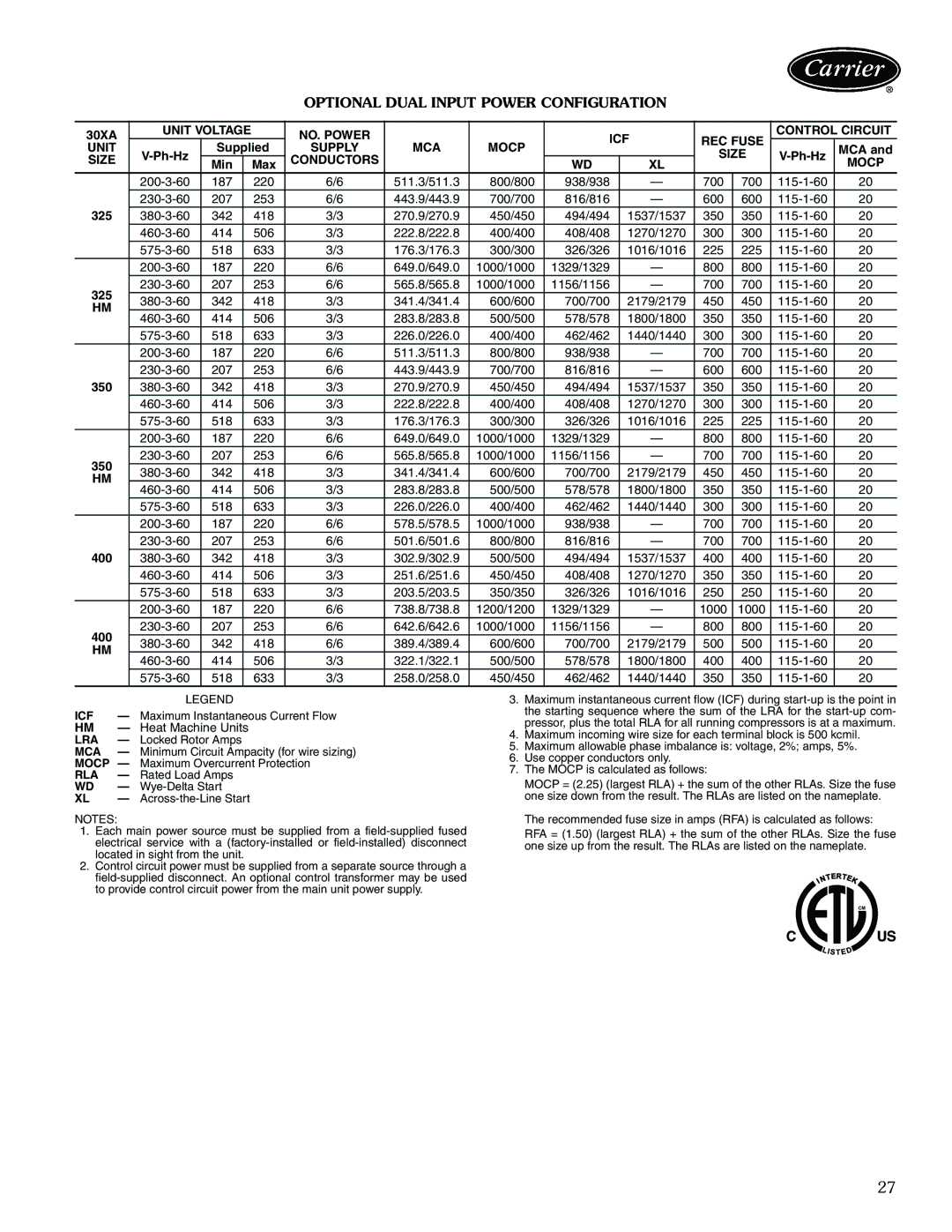
OPTIONAL DUAL INPUT POWER CONFIGURATION
30XA | UNIT VOLTAGE |
| NO. POWER |
|
| ICF | REC FUSE | CONTROL CIRCUIT | |||||
UNIT |
| Supplied | SUPPLY | MCA | MOCP |
| MCA and | ||||||
|
| SIZE | |||||||||||
SIZE |
|
|
| CONDUCTORS |
|
|
|
| |||||
| Min |
| Max |
|
| WD | XL |
|
|
| MOCP | ||
| 187 |
| 220 | 6/6 | 511.3/511.3 | 800/800 | 938/938 | — | 700 | 700 | 20 | ||
| 207 |
| 253 | 6/6 | 443.9/443.9 | 700/700 | 816/816 | — | 600 | 600 | 20 | ||
325 | 342 |
| 418 | 3/3 | 270.9/270.9 | 450/450 | 494/494 | 1537/1537 | 350 | 350 | 20 | ||
| 414 |
| 506 | 3/3 | 222.8/222.8 | 400/400 | 408/408 | 1270/1270 | 300 | 300 | 20 | ||
| 518 |
| 633 | 3/3 | 176.3/176.3 | 300/300 | 326/326 | 1016/1016 | 225 | 225 | 20 | ||
| 187 |
| 220 | 6/6 | 649.0/649.0 | 1000/1000 | 1329/1329 | — | 800 | 800 | 20 | ||
325 | 207 |
| 253 | 6/6 | 565.8/565.8 | 1000/1000 | 1156/1156 | — | 700 | 700 | 20 | ||
342 |
| 418 | 3/3 | 341.4/341.4 | 600/600 | 700/700 | 2179/2179 | 450 | 450 | 20 | |||
HM |
| ||||||||||||
414 |
| 506 | 3/3 | 283.8/283.8 | 500/500 | 578/578 | 1800/1800 | 350 | 350 | 20 | |||
|
| ||||||||||||
| 518 |
| 633 | 3/3 | 226.0/226.0 | 400/400 | 462/462 | 1440/1440 | 300 | 300 | 20 | ||
| 187 |
| 220 | 6/6 | 511.3/511.3 | 800/800 | 938/938 | — | 700 | 700 | 20 | ||
| 207 |
| 253 | 6/6 | 443.9/443.9 | 700/700 | 816/816 | — | 600 | 600 | 20 | ||
350 | 342 |
| 418 | 3/3 | 270.9/270.9 | 450/450 | 494/494 | 1537/1537 | 350 | 350 | 20 | ||
| 414 |
| 506 | 3/3 | 222.8/222.8 | 400/400 | 408/408 | 1270/1270 | 300 | 300 | 20 | ||
| 518 |
| 633 | 3/3 | 176.3/176.3 | 300/300 | 326/326 | 1016/1016 | 225 | 225 | 20 | ||
| 187 |
| 220 | 6/6 | 649.0/649.0 | 1000/1000 | 1329/1329 | — | 800 | 800 | 20 | ||
350 | 207 |
| 253 | 6/6 | 565.8/565.8 | 1000/1000 | 1156/1156 | — | 700 | 700 | 20 | ||
342 |
| 418 | 3/3 | 341.4/341.4 | 600/600 | 700/700 | 2179/2179 | 450 | 450 | 20 | |||
HM |
| ||||||||||||
414 |
| 506 | 3/3 | 283.8/283.8 | 500/500 | 578/578 | 1800/1800 | 350 | 350 | 20 | |||
|
| ||||||||||||
| 518 |
| 633 | 3/3 | 226.0/226.0 | 400/400 | 462/462 | 1440/1440 | 300 | 300 | 20 | ||
| 187 |
| 220 | 6/6 | 578.5/578.5 | 1000/1000 | 938/938 | — | 700 | 700 | 20 | ||
| 207 |
| 253 | 6/6 | 501.6/501.6 | 800/800 | 816/816 | — | 700 | 700 | 20 | ||
400 | 342 |
| 418 | 3/3 | 302.9/302.9 | 500/500 | 494/494 | 1537/1537 | 400 | 400 | 20 | ||
| 414 |
| 506 | 3/3 | 251.6/251.6 | 450/450 | 408/408 | 1270/1270 | 350 | 350 | 20 | ||
| 518 |
| 633 | 3/3 | 203.5/203.5 | 350/350 | 326/326 | 1016/1016 | 250 | 250 | 20 | ||
| 187 |
| 220 | 6/6 | 738.8/738.8 | 1200/1200 | 1329/1329 | — | 1000 | 1000 | 20 | ||
400 | 207 |
| 253 | 6/6 | 642.6/642.6 | 1000/1000 | 1156/1156 | — | 800 | 800 | 20 | ||
342 |
| 418 | 6/6 | 389.4/389.4 | 600/600 | 700/700 | 2179/2179 | 500 | 500 | 20 | |||
HM |
| ||||||||||||
414 |
| 506 | 3/3 | 322.1/322.1 | 500/500 | 578/578 | 1800/1800 | 400 | 400 | 20 | |||
|
| ||||||||||||
| 518 |
| 633 | 3/3 | 258.0/258.0 | 450/450 | 462/462 | 1440/1440 | 350 | 350 | 20 | ||
|
| LEGEND |
ICF | — | Maximum Instantaneous Current Flow |
HM | — Heat Machine Units | |
LRA | — | Locked Rotor Amps |
MCA | — | Minimum Circuit Ampacity (for wire sizing) |
MOCP — | Maximum Overcurrent Protection | |
RLA | — | Rated Load Amps |
WD | — | |
XL | — |
|
NOTES:
1.Each main power source must be supplied from a
2.Control circuit power must be supplied from a separate source through a
3.Maximum instantaneous current flow (ICF) during
4.Maximum incoming wire size for each terminal block is 500 kcmil.
5.Maximum allowable phase imbalance is: voltage, 2%; amps, 5%.
6.Use copper conductors only.
7.The MOCP is calculated as follows:
MOCP = (2.25) (largest RLA) + the sum of the other RLAs. Size the fuse one size down from the result. The RLAs are listed on the nameplate.
The recommended fuse size in amps (RFA) is calculated as follows:
RFA = (1.50) (largest RLA) + the sum of the other RLAs. Size the fuse one size up from the result. The RLAs are listed on the nameplate.
27