Application data
Unit storage
Store chiller and starter indoors, protected from construc- tion dirt and moisture. Inspect under shipping tarps, bags, or crates to be sure water has not collected during transit. Keep protective shipping covers in place until machine is ready for installation. Assure that the inside of the protec- tive cover meets the following criteria:
•Temperature is between 40 F (4.4 C) and 120 F (48.9 C)
•Relative humidity is between 10% and 80% (non- condensing)
Chiller location
Unit should be located indoors on a level surface in an area with temperatures between 50 F (10 C) and 104 F (40 C). Clearance should be provided around the unit for service and local code requirements. See dimensional drawings for specific unit clearance requirements. Consideration should be given to using
Relief valve vent lines:
1.Vent per local code requirements.
2.Each chiller has 2 relief valves on the evaporator, 2 on the condenser and one relief valve on each com- pressor discharge line.
Strainers
A screen strainer with minimum screen size of 20 mesh must be installed within 10 ft (3 m) of the inlet pipe con- nection to both the evaporator and condenser to prevent debris from damaging internal tubes of the evaporator. The pump strainer shall not be used to meet this requirement.
Oversizing chillers
Oversizing chillers by more than 15% at design conditions should be avoided as the system operating efficiency is adversely affected (resulting in greater or excessive electri- cal demand). When future expansion of equipment is antic- ipated, install a single chiller to meet present load requirements and add a second chiller to meet the addi- tional load demand. It is also recommended that 2 smaller chillers be installed where operation at minimum load is critical. The operation of a smaller chiller loaded to a greater percentage over minimum is preferred to operating a larger chiller at or near its minimum recommended value. Operation at its minimum load should only be done inter- mittently, not for long periods of time. Minimum load con- trol should not be used as a means to allow oversizing chillers.
Evaporator water temperature
Maximum leaving fluid temperature for the unit is 60 F (15.5 C). The unit can start and pull down with up to 95 F (35 C) entering fluid temperature. For sustained operation, it is recommended the fluid temperature not exceed 70 F (21.1 C). Water flowing through the evaporator should never exceed 100 F (37.8 C). Minimum leaving water tem- perature is 40 F (4.4 C).
Evaporator flow range
For minimum and maximum evaporator flow rates please see the Evaporator and Condenser Flow Rates table. A high flow rate is generally limited by the maximum pres- sure drop that can be tolerated by the unit. The 30XW chillers are designed for a full load temperature rise of 5 to 20 F (2.8 to 11.1 C). See the Carrier selection program for pressure drop values and performance.
Minimum evaporator flow
When system design conditions require a lower flow (or higher temperature rise) than the minimum allowable evap- orator flow rate, please follow the recommendations below.
•Multiple smaller chillers may be applied in series, each providing a portion of the design temperature rise.
•Try increasing the number of passes in the evaporator (1, 2, or 3 passes available).
•Evaporator fluid may be recirculated to raise the flow rate to the chiller. The mixed temperature entering the
evaporator must be maintained to a minimum of at least 5 ° F (2.8 ° C) above the leaving chilled fluid tempera- ture and a maximum of no more than 20 F (11.1 C) above the leaving chilled fluid temperature.
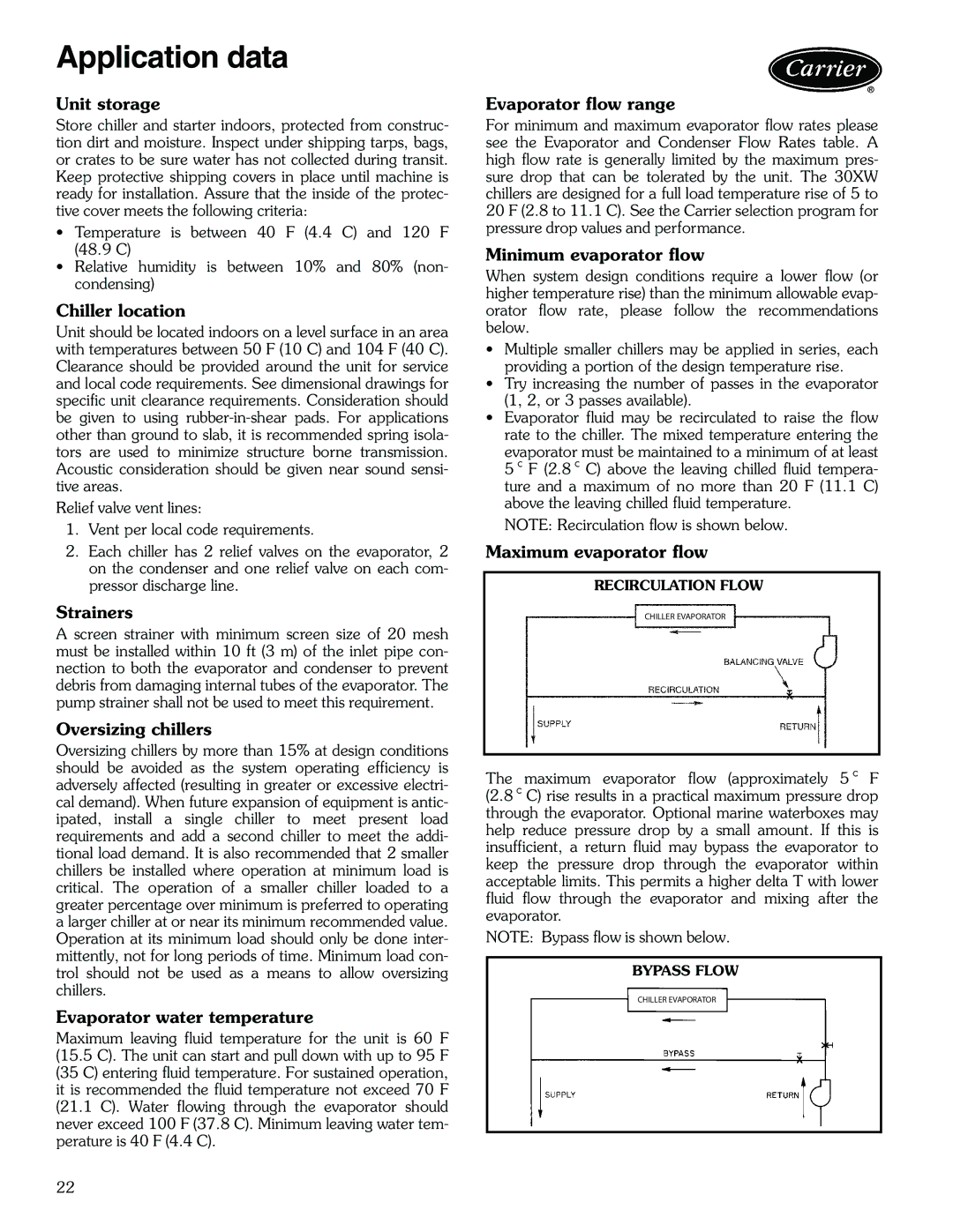
NOTE: Recirculation flow is shown below.
Maximum evaporator flow
RECIRCULATION FLOW
CHILLER EVAPORATOR
a30-4698
The maximum evaporator flow (approximately 5 ° F (2.8 ° C) rise results in a practical maximum pressure drop through the evaporator. Optional marine waterboxes may help reduce pressure drop by a small amount. If this is insufficient, a return fluid may bypass the evaporator to keep the pressure drop through the evaporator within acceptable limits. This permits a higher delta T with lower fluid flow through the evaporator and mixing after the evaporator.
NOTE: Bypass flow is shown below.
BYPASS FLOW
CHILLER EVAPORATOR
22