Unit Isolation Ð Where extremely quiet operation is essential, install isolators between ¯oor and base of unit, or between ceiling and top section of unit.
Be sure that unit is level and adequately supported. Use channels at front and sides of unit for reference points when leveling.
Refrigerant and Chilled Water Piping Access Ð
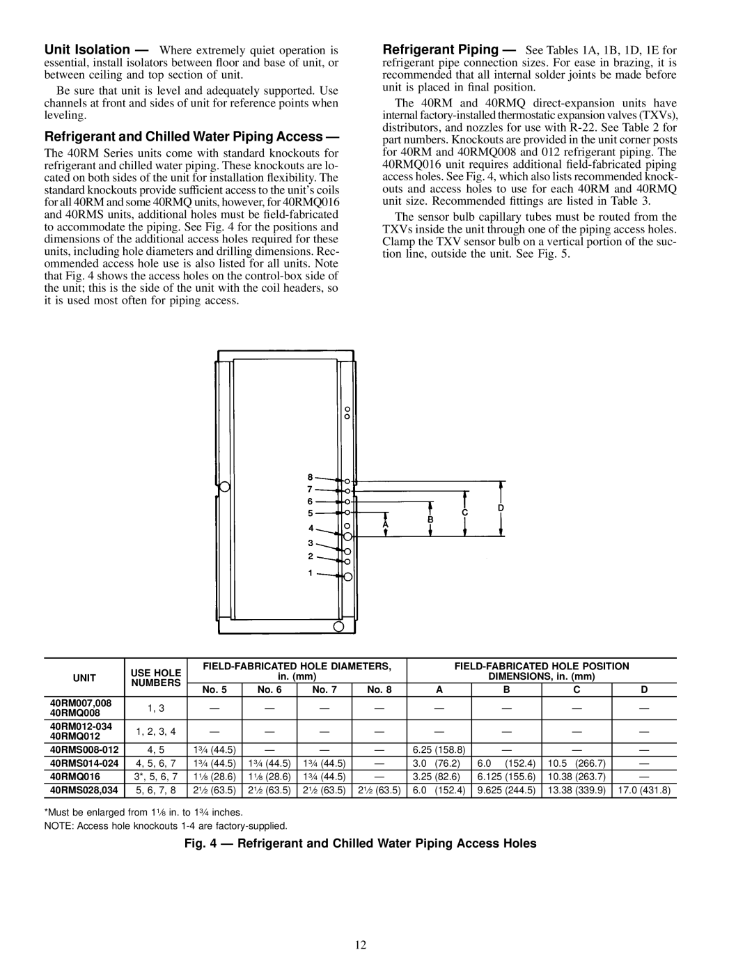
The 40RM Series units come with standard knockouts for refrigerant and chilled water piping. These knockouts are lo- cated on both sides of the unit for installation ¯exibility. The standard knockouts provide sufficient access to the unit's coils for all 40RM and some 40RMQ units, however, for 40RMQ016 and 40RMS units, additional holes must be
Refrigerant Piping Ð See Tables 1A, 1B, 1D, 1E for refrigerant pipe connection sizes. For ease in brazing, it is recommended that all internal solder joints be made before unit is placed in ®nal position.
The 40RM and 40RMQ
The sensor bulb capillary tubes must be routed from the TXVs inside the unit through one of the piping access holes. Clamp the TXV sensor bulb on a vertical portion of the suc- tion line, outside the unit. See Fig. 5.
| USE HOLE |
|
| |||||||||
UNIT |
| in. (mm) |
|
|
|
| DIMENSIONS, in. (mm) |
|
| |||
NUMBERS |
|
|
|
|
|
|
| |||||
| No. 5 | No. 6 | No. 7 | No. 8 |
|
| A | B | C |
| D | |
|
|
|
|
| ||||||||
40RM007,008 | 1, 3 | Ð | Ð | Ð | Ð |
| Ð |
| Ð | Ð | Ð | |
40RMQ008 |
|
| ||||||||||
|
|
|
|
|
|
|
|
|
|
|
| |
1, 2, 3, 4 | Ð | Ð | Ð | Ð |
| Ð |
| Ð | Ð | Ð | ||
40RMQ012 |
|
| ||||||||||
|
|
|
|
|
|
|
|
|
|
|
| |
4, 5 | 13¤4 (44.5) | Ð | Ð | Ð | 6.25 (158.8) | Ð | Ð | Ð | ||||
4, 5, 6, 7 | 13¤4 (44.5) | 13¤4 (44.5) | 13¤4 (44.5) | Ð | 3.0 | (76.2) | 6.0 (152.4) | 10.5 (266.7) | Ð | |||
40RMQ016 | 3*, 5, 6, 7 | 11¤8 (28.6) | 11¤8 (28.6) | 13¤4 (44.5) | Ð | 3.25 (82.6) | 6.125 (155.6) | 10.38 (263.7) | Ð | |||
40RMS028,034 | 5, 6, 7, 8 | 21¤2 (63.5) | 21¤2 (63.5) | 21¤2 (63.5) | 21¤2 (63.5) 6.0 | (152.4) | 9.625 (244.5) | 13.38 (339.9) | 17.0 (431.8) | |||
*Must be enlarged from 11¤8 in. to 13¤4 inches.
NOTE: Access hole knockouts
Fig. 4 Ð Refrigerant and Chilled Water Piping Access Holes
12