Table 3 Ð Fitting Requirements (cont)
UNIT | ACCESS | CONNECTION | CIRCUIT | FITTINGS REQUIRED² | ||
HOLE NO.* | TYPE |
| (in.) | |||
|
|
| ||||
| 5 | Supply | Lower | 21¤8 | Long Radius Elbow | |
| 21¤8 | Nipple, 31¤2 L | ||||
|
|
|
| 21¤8 | Long Radius Elbow | |
|
|
|
| 21¤8 | Long Radius Elbow | |
| 6 | Return | Lower | 21¤8 | Nipple, 3 L | |
40RMS |
|
|
| 21¤8 | Long Radius Elbow | |
028, 034 | 7 | Return | Upper | 21¤8 | Long Radius Elbow | |
| 21¤8 | Nipple, 67¤8 L | ||||
|
|
|
| 21¤8 | Long Radius Elbow | |
|
|
|
| 21¤8 | Long Radius Elbow | |
| 8 | Supply | Upper | 21¤8 | Nipple, 117¤8 L | |
|
|
|
| 21¤8 | Long Radius Elbow | |
| 1 | Suction | Lower | 13¤8 | Street Elbow | |
| 13¤8 | Nipple, 3 L | ||||
|
|
|
| 13¤8 | Long Radius Elbow | |
| 2 | Liquid | Lower | 5¤8 | Street Elbow | |
| 5¤8 | Nipple, 73¤4 L | ||||
40RM |
|
|
| 5¤8 | Long Radius Elbow | |
|
|
| 5¤8 | Street Elbow | ||
034 | 3 | Liquid | Upper | |||
5¤8 | Nipple, 181¤2 L | |||||
| ||||||
|
|
|
| 5¤8 | Long Radius Elbow | |
|
|
|
| 13¤8 | Nipple, 43¤16 L | |
| 4 | Suction | Upper | 13¤8 | Long Radius Elbow | |
| 13¤8 | Nipple, 191¤4 L | ||||
|
|
|
| |||
|
|
|
| 13¤8 | Long Radius Elbow | |
*See Fig. 4 for access hole location by number.
²Fittings are listed in order from header or tee stub connection out to access hole in corner support post.
Chilled Water Piping Ð See Tables 1C and 1F for chilled water connection sizes. For ease in brazing, it is rec- ommended that all internal solder joints be made before unit is placed in ®nal position.
Knockouts are provided in the unit corner posts for 40RM and 40RMQ refrigerant piping; additional
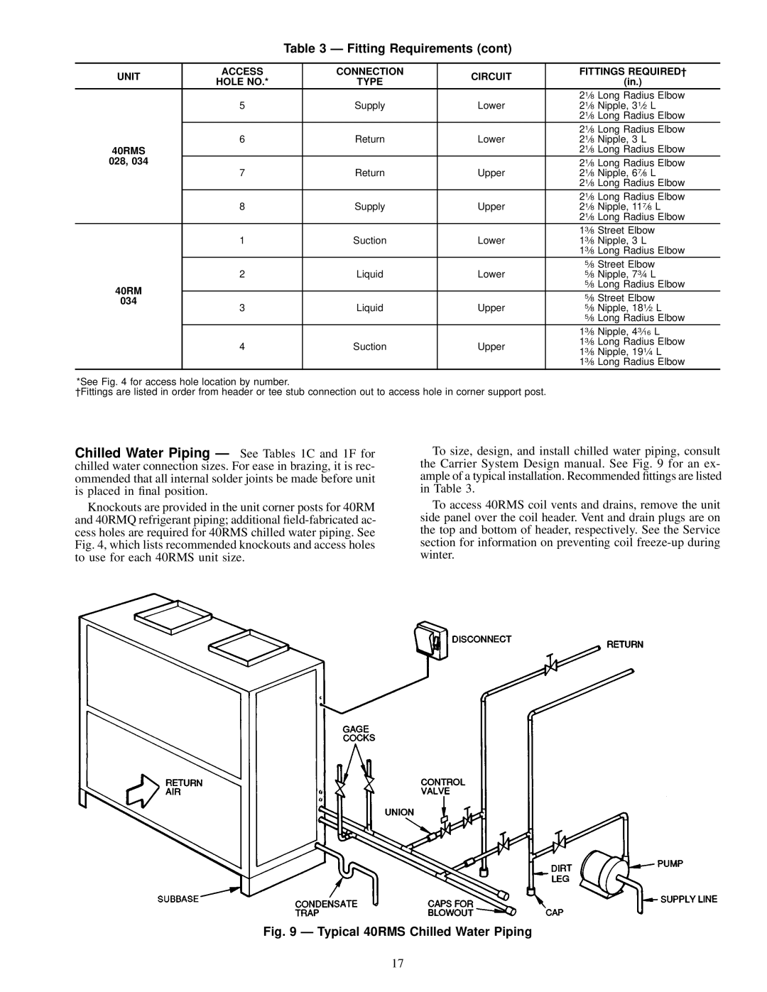
To size, design, and install chilled water piping, consult the Carrier System Design manual. See Fig. 9 for an ex- ample of a typical installation. Recommended ®ttings are listed in Table 3.
To access 40RMS coil vents and drains, remove the unit side panel over the coil header. Vent and drain plugs are on the top and bottom of header, respectively. See the Service section for information on preventing coil
Fig. 9 Ð Typical 40RMS Chilled Water Piping
17