Contents
Installation, Start-Up Service Instructions
Ð 40RM Physical Data, English
Unit 40RMQ
Ð 40RMQ Physical Data, English
Unit 40RMS
Ð 40RMS Physical Data, English
Chilled Water Coil
Ð 40RM Physical Data, SI
Ð 40RMQ Physical Data, SI
Ð 40RMS Physical Data, SI
Unit Unit Weight
Ð Dimensions Ð Sizes
40RM014
Ð Dimensions Ð Sizes 028,034
40RMQ 40RMS
Unit
Numbers
Refrigerant and Chilled Water Piping Access Holes
Face-Split Coil Suction Liquid Line Piping Typical
TXV Distributor Feeder Tubes Nozzle Unit PER Distributor
Factory-Installed Nozzle and Distributor Data
Liquid Unit Line Quantity 38AQS Size Required Reference
40RMQ
Fitting Requirements
11¤8 Street Elbow Nipple, 23¤4 L Long Radius Elbow Liquid
Typical 40RMS Chilled Water Piping
Condensate Drains
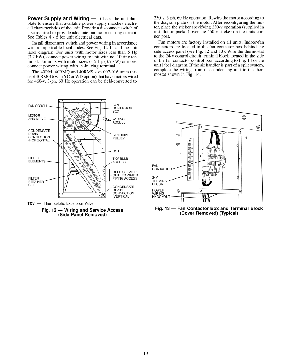
Wiring and Service Access Side Panel Removed
Mocp
Voltage FAN Motor Power Supply Unit PH-HZ
Electrical Data, Standard Motors
FLA
FLA Ð
Electrical Data, Alternate Motors
Mocp Ð
Fan Contactor Coil Data
Manufacturer Lubricant
Lubricant Data
Fan Shaft Bearing
Fan Pulley Alignment Ð Align as follows
40RMS 40RMQ Unit
Ð Fan Motor Data, Standard Motor Ð English
Ð Fan Motor Data, Alternate Motor Ð English
40RMQ 40RMS Unit
Ð Fan Motor Data, Alternate Motor Ð SI
Ð Fan Motor Data, Standard Motor Ð SI
FAN Drive
Ð Standard Drive Data, 60 Hz Ð English
Ð Medium-Static Drive Data, 60 Hz Ð English
Motor Drive
Ð Standard Drive Data, 50 Hz Ð English
Ð High-Static Drive Data, 60 Hz Ð English
Ð High-Static Drive Data, 50 Hz Ð English
Ð Medium-Static Drive Data, 50 Hz Ð English
Ð Medium-Static Drive Data, 60 Hz Ð SI
Ð Standard Drive Data, 60 Hz Ð SI
40RMQ Unit
Ð Standard Drive Data, 50 Hz Ð SI
Ð High-Static Drive Data, 60 Hz Ð SI
Ð High-Static Drive Data, 50 Hz Ð SI
Ð Medium-Static Drive Data, 50 Hz Ð SI
Airflow
Ð Fan Performance Data Ð 0.0-1.2 in. wg ESP Ð English
Ð Fan Performance Data Ð 1.4-2.4 in. wg ESP Ð English
Unit Airflow Pressure Drop
Ð Fan Performance Data Ð 0-300 Pa ESP Ð SI
Ð Fan Performance Data Ð 350-600 Pa ESP Ð SI
Filter Removal/Replacement
Page
Page
Copyright 1995 Carrier Corporation
START-UP Checklist
Comp A1 Comp B1
Check Voltage Imbalance