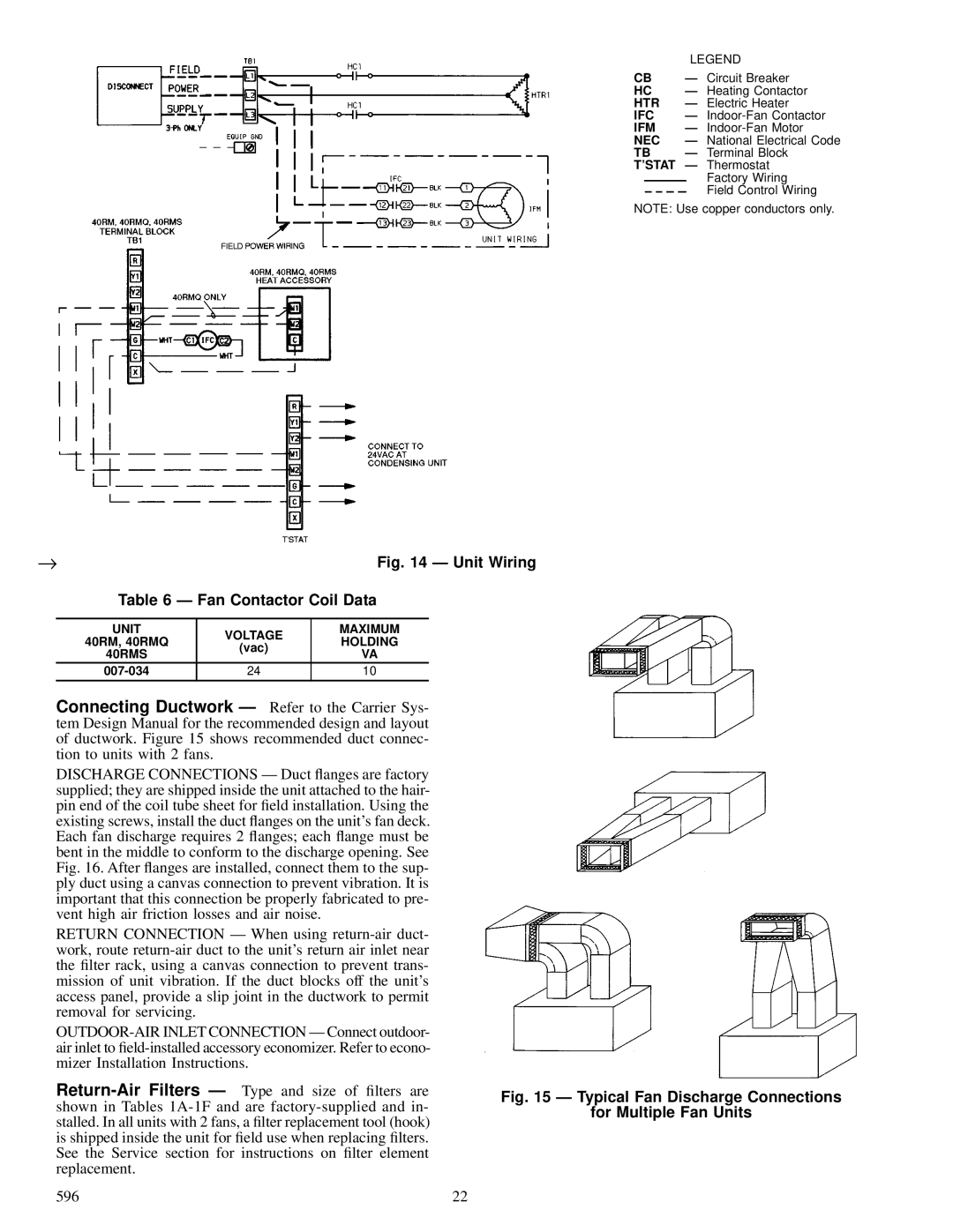
| LEGEND | |
CB | Ð Circuit Breaker | |
HC | Ð Heating Contactor | |
HTR | Ð Electric Heater | |
IFC | Ð | |
IFM | Ð | |
NEC | Ð National Electrical Code | |
TB | Ð Terminal Block | |
T'STAT | Ð | Thermostat |
|
| Factory Wiring |
|
| Field Control Wiring |
NOTE: Use copper conductors only.
→ | Fig. 14 Ð Unit Wiring |
| Table 6 Ð Fan Contactor Coil Data |
UNIT | VOLTAGE | MAXIMUM | |
40RM, 40RMQ | HOLDING | ||
(vac) | |||
40RMS | VA | ||
| |||
24 | 10 | ||
|
|
|
Connecting Ductwork Ð Refer to the Carrier Sys- tem Design Manual for the recommended design and layout of ductwork. Figure 15 shows recommended duct connec- tion to units with 2 fans.
DISCHARGE CONNECTIONS Ð Duct ¯anges are factory supplied; they are shipped inside the unit attached to the hair- pin end of the coil tube sheet for ®eld installation. Using the existing screws, install the duct ¯anges on the unit's fan deck. Each fan discharge requires 2 ¯anges; each ¯ange must be bent in the middle to conform to the discharge opening. See Fig. 16. After ¯anges are installed, connect them to the sup- ply duct using a canvas connection to prevent vibration. It is important that this connection be properly fabricated to pre- vent high air friction losses and air noise.
RETURN CONNECTION Ð When using
596 | 22 |