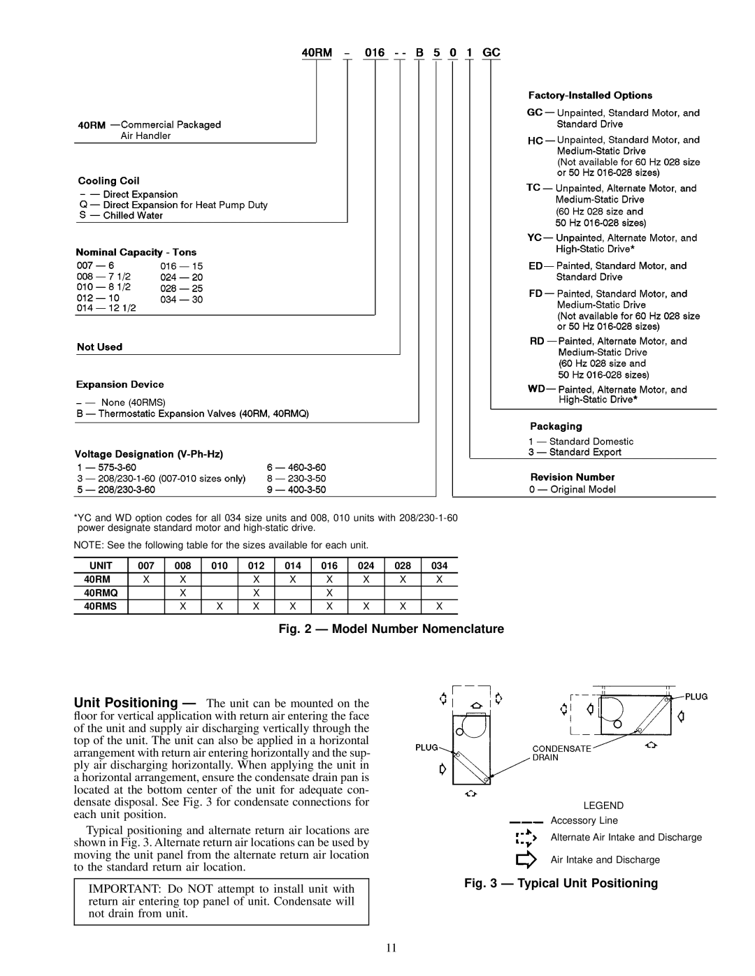
*YC and WD option codes for all 034 size units and 008, 010 units with
NOTE: See the following table for the sizes available for each unit.
UNIT | 007 | 008 | 010 | 012 | 014 | 016 | 024 | 028 | 034 |
40RM | X | X |
| X | X | X | X | X | X |
40RMQ |
| X |
| X |
| X |
|
|
|
40RMS |
| X | X | X | X | X | X | X | X |
|
|
|
|
|
|
|
|
|
|
Fig. 2 Ð Model Number Nomenclature
Unit Positioning Ð The unit can be mounted on the ¯oor for vertical application with return air entering the face of the unit and supply air discharging vertically through the top of the unit. The unit can also be applied in a horizontal arrangement with return air entering horizontally and the sup- ply air discharging horizontally. When applying the unit in a horizontal arrangement, ensure the condensate drain pan is located at the bottom center of the unit for adequate con- densate disposal. See Fig. 3 for condensate connections for each unit position.
Typical positioning and alternate return air locations are shown in Fig. 3. Alternate return air locations can be used by moving the unit panel from the alternate return air location to the standard return air location.
LEGEND
Accessory Line
Alternate Air Intake and Discharge
Air Intake and Discharge
IMPORTANT: Do NOT attempt to install unit with return air entering top panel of unit. Condensate will not drain from unit.
Fig. 3 Ð Typical Unit Positioning
11