Duct Covers
A05301
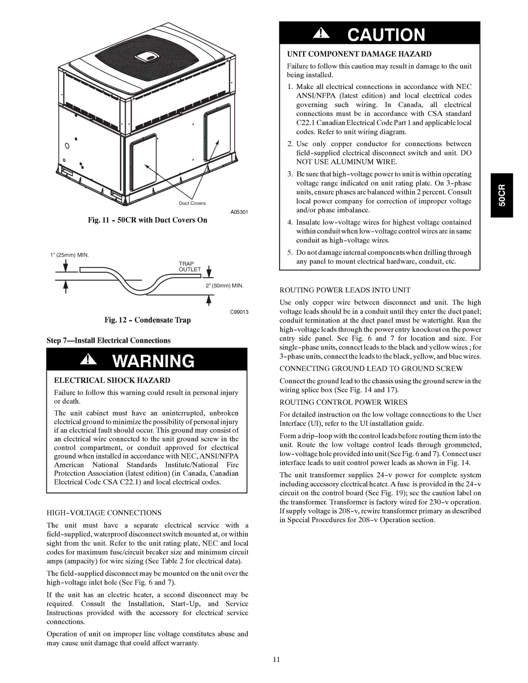
Fig. 11 - 50CR with Duct Covers On
1” (25mm) MIN.
TRAP
OUTLET
2” (50mm) MIN.
C99013
Fig. 12 - Condensate Trap
Step 7—Install Electrical Connections
!WARNING
ELECTRICAL SHOCK HAZARD
Failure to follow this warning could result in personal injury or death.
The unit cabinet must have an uninterrupted, unbroken electrical ground to minimize the possibility of personal injury if an electrical fault should occur. This ground may consist of an electrical wire connected to the unit ground screw in the control compartment, or conduit approved for electrical ground when installed in accordance with NEC, ANSI/NFPA American National Standards Institute/National Fire Protection Association (latest edition) (in Canada, Canadian Electrical Code CSA C22.1) and local electrical codes.
HIGH-VOLTAGE CONNECTIONS
The unit must have a separate electrical service with a
The
If the unit has an electric heater, a second disconnect may be required. Consult the Installation,
Operation of unit on improper line voltage constitutes abuse and may cause unit damage that could affect warranty.
!CAUTION
UNIT COMPONENT DAMAGE HAZARD
Failure to follow this caution may result in damage to the unit being installed.
1.Make all electrical connections in accordance with NEC ANSI/NFPA (latest edition) and local electrical codes governing such wiring. In Canada, all electrical connections must be in accordance with CSA standard C22.1 Canadian Electrical Code Part 1 and applicable local codes. Refer to unit wiring diagram.
2.Use only copper conductor for connections between
3.Be sure that
4.Insulate
5.Do not damage internal components when drilling through any panel to mount electrical hardware, conduit, etc.
ROUTING POWER LEADS INTO UNIT
Use only copper wire between disconnect and unit. The high voltage leads should be in a conduit until they enter the duct panel; conduit termination at the duct panel must be watertight. Run the
CONNECTING GROUND LEAD TO GROUND SCREW
Connect the ground lead to the chassis using the ground screw in the wiring splice box (See Fig. 14 and 17).
ROUTING CONTROL POWER WIRES
For detailed instruction on the low voltage connections to the User Interface (UI), refer to the UI installation guide.
Form a
The unit transformer supplies
50CR
11