50CR
Table 1—Physical Data - Unit 50CR
UNIT SIZE | 024 | 030 | 036 | 042 |
|
| 048 | 060 |
NOMINAL CAPACITY (ton) | 2 | 3 |
|
| 4 | 5 | ||
OPERATING WEIGHT (lb.) | 350 | 350 | 373 | 440 |
|
| 463 | 499 |
Compressor |
|
|
|
|
| Scroll |
|
|
Refrigerant | 7.5 | 8 | 9.5 | 10.8 |
|
| 11.5 | 14.0 |
REFRIGERANT METERING DEVICE |
|
|
|
|
| TXV |
|
|
ORIFICE OD (in.) | 0.035 (2) | 0.035 (2) | 0.038 (2) | 0.038 (2) |
| 0.038 (Left OD Coil) | 0.042 (Left OD Coil) | |
| 0.046 (Right OD Coil) | 0.052 (Right OD Coil) | ||||||
|
|
|
|
|
| |||
|
|
|
|
|
|
|
|
|
OUTDOOR COIL |
|
|
|
|
|
|
|
|
Rows…Fins/in. | 2…21 | 2…21 | 2…21 | 2…21 |
|
| 2…21 | 2…21 |
Face Area (sq. ft.) | 12.3 | 12.3 | 13.6 | 15.4 |
|
| 17.2 | 19.4 |
OUTDOOR FAN |
|
|
|
|
|
|
|
|
Nominal Cfm | 2700 | 2700 | 2800 | 2800 |
|
| 3300 | 3300 |
Diameter | 22 | 22 | 22 | 22 |
|
| 22 | 22 |
Motor HP (RPM) | 1/8 (825) | 1/8 (825) | 1/8 (825) | 1/8 (825) |
|
| 1/4 (1100) | 1/4 (1100) |
|
|
|
|
|
|
|
|
|
INDOOR COIL |
|
|
|
|
|
|
|
|
Rows…Fins/in. | 3…15 | 3…15 | 4…15 | 3…15 |
|
| 4…15 | 4…17 |
Face Area (sq. ft.) | 3.7 | 3.7 | 3.7 | 4.7 |
|
| 4.7 | 5.7 |
INDOOR BLOWER |
|
|
|
|
|
|
|
|
Nominal Airflow (Cfm) |
|
|
|
|
|
|
|
|
Comfort | Variable based on Comfort Roll back (see User Interface instructions for more information). | |||||||
Efficiency | 700 | 875 | 1050 | 1225 |
|
| 1400 | 1750 |
Max | 800 | 1000 | 1200 | 1400 |
|
| 1600 | 2000 |
Size (in.) | 10x10 | 10x10 | 11x10 | 11x10 |
|
| 11x10 | 11x10 |
Motor HP (RPM) | 1/2 | 1/2 | 3/4 | 3/4 |
|
| 3/4 | 1 |
|
|
|
|
|
|
|
|
|
|
|
| 650 ± 15 |
|
| |||
Cutout |
|
|
|
|
| |||
|
|
| 420 ± 25 |
|
| |||
Reset (Auto) |
|
|
|
|
| |||
|
|
|
|
|
|
|
| |
|
|
|
|
|
|
|
|
|
|
|
|
|
|
|
|
|
|
(Liquid Line) (psig) |
|
|
|
| 20 ± 5 |
|
| |
Cutout |
|
|
| 45 ± 10 |
|
| ||
Reset (Auto) |
|
|
|
|
|
|
|
|
|
|
|
|
|
|
|
|
|
20x24x1 | 20x24x1 | 24x30x1 | 24x36x1 |
|
| 24x36x1 | 24x36x1 | |
Throwaway |
|
| ||||||
|
|
|
|
|
|
|
| |
|
|
|
|
|
|
| ||
*Required filter sizes shown are based on the larger of the ARI | (Air Conditioning and Refrigeration Institute) rated cooling airflow or the heating airflow velocity of 300 ft/minute | |||||||
for throwaway type or 450 ft/minute for |
| |||||||
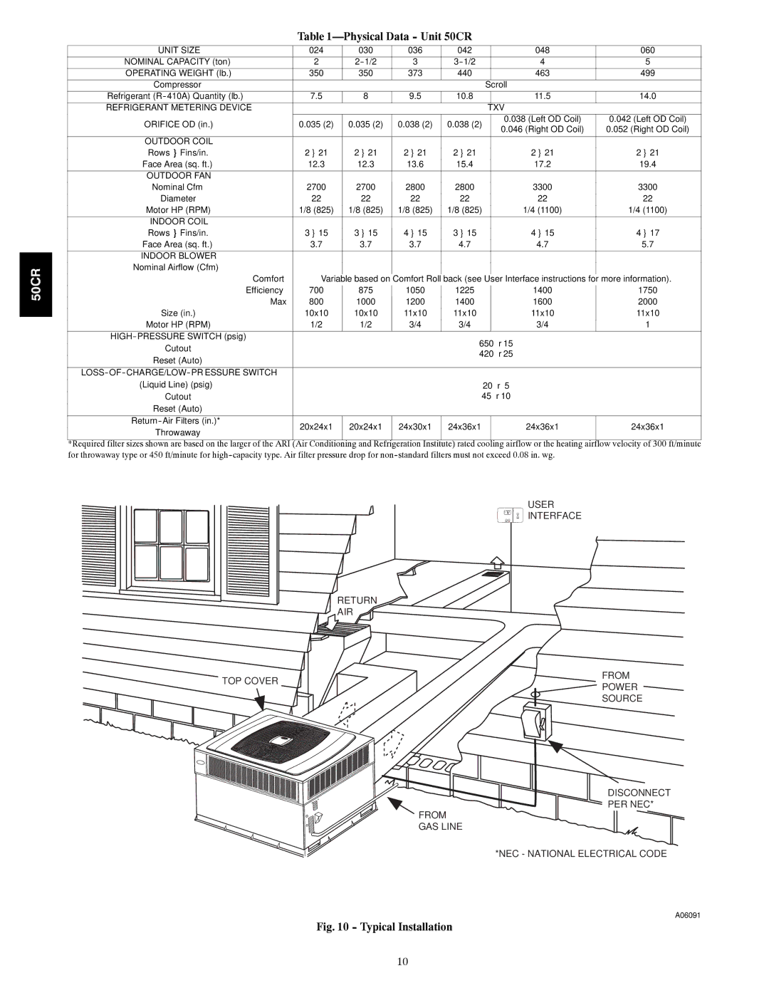
USER
![]() INTERFACE
INTERFACE
RETURN
AIR
TOP COVER
FROM
POWER
SOURCE
DISCONNECT PER NEC*
FROM
GAS LINE
*NEC - NATIONAL ELECTRICAL CODE
A06091
Fig. 10 - Typical Installation
10