|
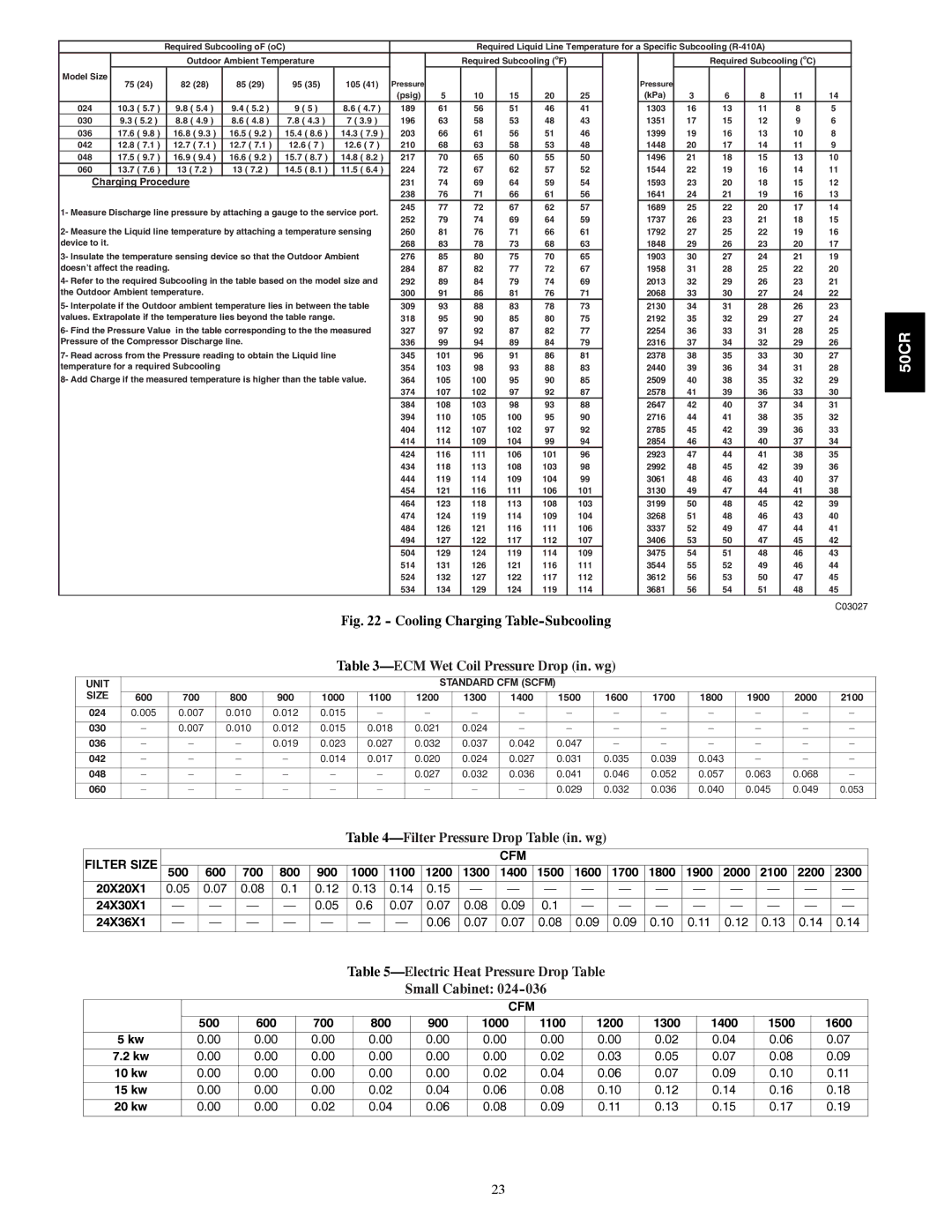
| Required Subcooling oF (oC) |
|
|
|
|
| Required Liquid Line Temperature for a Specific Subcooling |
|
| |||||||||||
|
|
| Outdoor Ambient Temperature |
|
|
| Required Subcooling (oF) |
|
|
|
| Required Subcooling (oC) |
| ||||||||
Model Size | 75 (24) |
| 82 (28) | 85 (29) |
| 95 (35) |
| 105 (41) | Pressure |
|
|
|
|
|
| Pressure |
|
|
|
|
|
|
|
|
|
|
|
|
|
|
|
|
|
|
|
| |||||||
|
|
|
|
|
|
|
|
| (psig) | 5 | 10 | 15 | 20 | 25 |
| (kPa) | 3 | 6 | 8 | 11 | 14 |
024 | 10.3 ( 5.7 ) |
| 9.8 ( 5.4 ) | 9.4 ( 5.2 ) |
| 9 ( 5 ) |
| 8.6 ( 4.7 ) | 189 | 61 | 56 | 51 | 46 | 41 |
| 1303 | 16 | 13 | 11 | 8 | 5 |
030 | 9.3 ( 5.2 ) |
| 8.8 ( 4.9 ) | 8.6 ( 4.8 ) |
| 7.8 ( 4.3 ) |
| 7 ( 3.9 ) | 196 | 63 | 58 | 53 | 48 | 43 |
| 1351 | 17 | 15 | 12 | 9 | 6 |
036 | 17.6 ( 9.8 ) |
| 16.8 ( 9.3 ) | 16.5 ( 9.2 ) |
| 15.4 ( 8.6 ) |
| 14.3 ( 7.9 ) | 203 | 66 | 61 | 56 | 51 | 46 |
| 1399 | 19 | 16 | 13 | 10 | 8 |
042 | 12.8 ( 7.1 ) |
| 12.7 ( 7.1 ) | 12.7 ( 7.1 ) |
| 12.6 ( 7 ) |
| 12.6 ( 7 ) | 210 | 68 | 63 | 58 | 53 | 48 |
| 1448 | 20 | 17 | 14 | 11 | 9 |
048 | 17.5 ( 9.7 ) |
| 16.9 ( 9.4 ) | 16.6 ( 9.2 ) |
| 15.7 ( 8.7 ) |
| 14.8 ( 8.2 ) | 217 | 70 | 65 | 60 | 55 | 50 |
| 1496 | 21 | 18 | 15 | 13 | 10 |
060 | 13.7 ( 7.6 ) |
| 13 ( 7.2 ) | 13 ( 7.2 ) |
| 14.5 ( 8.1 ) |
| 11.5 ( 6.4 ) | 224 | 72 | 67 | 62 | 57 | 52 |
| 1544 | 22 | 19 | 16 | 14 | 11 |
Charging Procedure |
|
|
|
|
| 231 | 74 | 69 | 64 | 59 | 54 |
| 1593 | 23 | 20 | 18 | 15 | 12 | |||
|
|
|
|
|
|
|
|
| 238 | 76 | 71 | 66 | 61 | 56 |
| 1641 | 24 | 21 | 19 | 16 | 13 |
1- Measure Discharge line pressure by attaching a gauge to the service port. | 245 | 77 | 72 | 67 | 62 | 57 |
| 1689 | 25 | 22 | 20 | 17 | 14 | ||||||||
252 | 79 | 74 | 69 | 64 | 59 |
| 1737 | 26 | 23 | 21 | 18 | 15 | |||||||||
|
|
|
|
|
|
|
|
|
| ||||||||||||
2- Measure the Liquid line temperature by attaching a temperature sensing | 260 | 81 | 76 | 71 | 66 | 61 |
| 1792 | 27 | 25 | 22 | 19 | 16 | ||||||||
device to it. |
|
|
|
|
|
|
|
| 268 | 83 | 78 | 73 | 68 | 63 |
| 1848 | 29 | 26 | 23 | 20 | 17 |
3- Insulate the temperature sensing device so that the Outdoor Ambient | 276 | 85 | 80 | 75 | 70 | 65 |
| 1903 | 30 | 27 | 24 | 21 | 19 | ||||||||
doesn’t affect the reading. |
|
|
|
|
| 284 | 87 | 82 | 77 | 72 | 67 |
| 1958 | 31 | 28 | 25 | 22 | 20 | |||
4- Refer to the required Subcooling in the table based on the model size and | 292 | 89 | 84 | 79 | 74 | 69 |
| 2013 | 32 | 29 | 26 | 23 | 21 | ||||||||
the Outdoor Ambient temperature. |
|
|
|
|
| 300 | 91 | 86 | 81 | 76 | 71 |
| 2068 | 33 | 30 | 27 | 24 | 22 | |||
5- Interpolate if the Outdoor ambient temperature lies in between the table | 309 | 93 | 88 | 83 | 78 | 73 |
| 2130 | 34 | 31 | 28 | 26 | 23 | ||||||||
values. Extrapolate if the temperature lies beyond the table range. |
| 318 | 95 | 90 | 85 | 80 | 75 |
| 2192 | 35 | 32 | 29 | 27 | 24 | |||||||
6- Find the Pressure Value in the table corresponding to the the measured | 327 | 97 | 92 | 87 | 82 | 77 |
| 2254 | 36 | 33 | 31 | 28 | 25 | ||||||||
Pressure of the Compressor Discharge line. |
|
|
| 336 | 99 | 94 | 89 | 84 | 79 |
| 2316 | 37 | 34 | 32 | 29 | 26 | |||||
7- Read across from the Pressure reading to obtain the Liquid line |
| 345 | 101 | 96 | 91 | 86 | 81 |
| 2378 | 38 | 35 | 33 | 30 | 27 | |||||||
temperature for a required Subcooling |
|
|
|
|
| 354 | 103 | 98 | 93 | 88 | 83 |
| 2440 | 39 | 36 | 34 | 31 | 28 | |||
8- Add Charge if the measured temperature is higher than the table value. | 364 | 105 | 100 | 95 | 90 | 85 |
| 2509 | 40 | 38 | 35 | 32 | 29 | ||||||||
|
|
|
|
|
|
|
|
| 374 | 107 | 102 | 97 | 92 | 87 |
| 2578 | 41 | 39 | 36 | 33 | 30 |
|
|
|
|
|
|
|
|
| 384 | 108 | 103 | 98 | 93 | 88 |
| 2647 | 42 | 40 | 37 | 34 | 31 |
|
|
|
|
|
|
|
|
| 394 | 110 | 105 | 100 | 95 | 90 |
| 2716 | 44 | 41 | 38 | 35 | 32 |
|
|
|
|
|
|
|
|
| 404 | 112 | 107 | 102 | 97 | 92 |
| 2785 | 45 | 42 | 39 | 36 | 33 |
|
|
|
|
|
|
|
|
| 414 | 114 | 109 | 104 | 99 | 94 |
| 2854 | 46 | 43 | 40 | 37 | 34 |
|
|
|
|
|
|
|
|
| 424 | 116 | 111 | 106 | 101 | 96 |
| 2923 | 47 | 44 | 41 | 38 | 35 |
|
|
|
|
|
|
|
|
| 434 | 118 | 113 | 108 | 103 | 98 |
| 2992 | 48 | 45 | 42 | 39 | 36 |
|
|
|
|
|
|
|
|
| 444 | 119 | 114 | 109 | 104 | 99 |
| 3061 | 48 | 46 | 43 | 40 | 37 |
|
|
|
|
|
|
|
|
| 454 | 121 | 116 | 111 | 106 | 101 |
| 3130 | 49 | 47 | 44 | 41 | 38 |
|
|
|
|
|
|
|
|
| 464 | 123 | 118 | 113 | 108 | 103 |
| 3199 | 50 | 48 | 45 | 42 | 39 |
|
|
|
|
|
|
|
|
| 474 | 124 | 119 | 114 | 109 | 104 |
| 3268 | 51 | 48 | 46 | 43 | 40 |
|
|
|
|
|
|
|
|
| 484 | 126 | 121 | 116 | 111 | 106 |
| 3337 | 52 | 49 | 47 | 44 | 41 |
|
|
|
|
|
|
|
|
| 494 | 127 | 122 | 117 | 112 | 107 |
| 3406 | 53 | 50 | 47 | 45 | 42 |
|
|
|
|
|
|
|
|
| 504 | 129 | 124 | 119 | 114 | 109 |
| 3475 | 54 | 51 | 48 | 46 | 43 |
|
|
|
|
|
|
|
|
| 514 | 131 | 126 | 121 | 116 | 111 |
| 3544 | 55 | 52 | 49 | 46 | 44 |
|
|
|
|
|
|
|
|
| 524 | 132 | 127 | 122 | 117 | 112 |
| 3612 | 56 | 53 | 50 | 47 | 45 |
|
|
|
|
|
|
|
|
| 534 | 134 | 129 | 124 | 119 | 114 |
| 3681 | 56 | 54 | 51 | 48 | 45 |
C03027
Fig. 22 - Cooling Charging Table-Subcooling
Table 3—ECM Wet Coil Pressure Drop (in. wg)
UNIT |
|
|
|
|
|
| STANDARD CFM (SCFM) |
|
|
|
|
|
|
| |||
SIZE |
|
|
|
|
|
|
|
|
|
|
|
|
|
|
|
|
|
600 | 700 | 800 | 900 | 1000 | 1100 | 1200 | 1300 | 1400 |
| 1500 | 1600 | 1700 | 1800 | 1900 | 2000 | 2100 | |
|
|
|
|
|
|
|
|
|
|
|
|
|
|
|
|
|
|
024 | 0.005 | 0.007 | 0.010 | 0.012 | 0.015 | – | – | – | – |
| – | – | – | – | – | – | – |
|
|
|
|
|
|
|
|
|
|
|
|
|
|
|
|
|
|
030 | – | 0.007 | 0.010 | 0.012 | 0.015 | 0.018 | 0.021 | 0.024 | – |
| – | – | – | – | – | – | – |
|
|
|
|
|
|
|
|
|
|
|
|
|
|
|
|
|
|
036 | – | – | – | 0.019 | 0.023 | 0.027 | 0.032 | 0.037 | 0.042 |
| 0.047 | – | – | – | – | – | – |
|
|
|
|
|
|
|
|
|
|
|
|
|
|
|
|
|
|
042 | – | – | – | – | 0.014 | 0.017 | 0.020 | 0.024 | 0.027 |
| 0.031 | 0.035 | 0.039 | 0.043 | – | – | – |
|
|
|
|
|
|
|
|
|
|
|
|
|
|
|
|
|
|
048 | – | – | – | – | – | – | 0.027 | 0.032 | 0.036 |
| 0.041 | 0.046 | 0.052 | 0.057 | 0.063 | 0.068 | – |
060 | – | – | – | – | – | – | – | – | – |
| 0.029 | 0.032 | 0.036 | 0.040 | 0.045 | 0.049 | 0.053 |
|
|
|
|
|
|
|
|
|
|
|
|
|
|
|
|
|
|
Table 4—Filter Pressure Drop Table (in. wg)
FILTER SIZE |
|
|
|
|
|
|
|
|
| CFM |
|
|
|
|
|
|
|
|
|
500 | 600 | 700 | 800 | 900 | 1000 | 1100 | 1200 | 1300 | 1400 | 1500 | 1600 | 1700 | 1800 | 1900 | 2000 | 2100 | 2200 | 2300 | |
20X20X1 | 0.05 | 0.07 | 0.08 | 0.1 | 0.12 | 0.13 | 0.14 | 0.15 | — | — | — | — | — | — | — | — | — | — | — |
|
|
|
|
|
|
|
|
|
|
|
|
|
|
|
|
|
|
|
|
24X30X1 | — | — | — | — | 0.05 | 0.6 | 0.07 | 0.07 | 0.08 | 0.09 | 0.1 | — | — | — | — | — | — | — | — |
24X36X1 | — | — | — | — | — | — | — | 0.06 | 0.07 | 0.07 | 0.08 | 0.09 | 0.09 | 0.10 | 0.11 | 0.12 | 0.13 | 0.14 | 0.14 |
|
|
|
|
|
|
|
|
|
|
|
|
|
|
|
|
|
|
|
|
Table 5—Electric Heat Pressure Drop Table
Small Cabinet: 024-036
|
|
|
|
|
|
| CFM |
|
|
|
|
|
| 500 | 600 | 700 | 800 | 900 | 1000 | 1100 | 1200 | 1300 | 1400 | 1500 | 1600 |
5 kw | 0.00 | 0.00 | 0.00 | 0.00 | 0.00 | 0.00 | 0.00 | 0.00 | 0.02 | 0.04 | 0.06 | 0.07 |
7.2 kw | 0.00 | 0.00 | 0.00 | 0.00 | 0.00 | 0.00 | 0.02 | 0.03 | 0.05 | 0.07 | 0.08 | 0.09 |
10 kw | 0.00 | 0.00 | 0.00 | 0.00 | 0.00 | 0.02 | 0.04 | 0.06 | 0.07 | 0.09 | 0.10 | 0.11 |
15 kw | 0.00 | 0.00 | 0.00 | 0.02 | 0.04 | 0.06 | 0.08 | 0.10 | 0.12 | 0.14 | 0.16 | 0.18 |
20 kw | 0.00 | 0.00 | 0.02 | 0.04 | 0.06 | 0.08 | 0.09 | 0.11 | 0.13 | 0.15 | 0.17 | 0.19 |
50CR
23