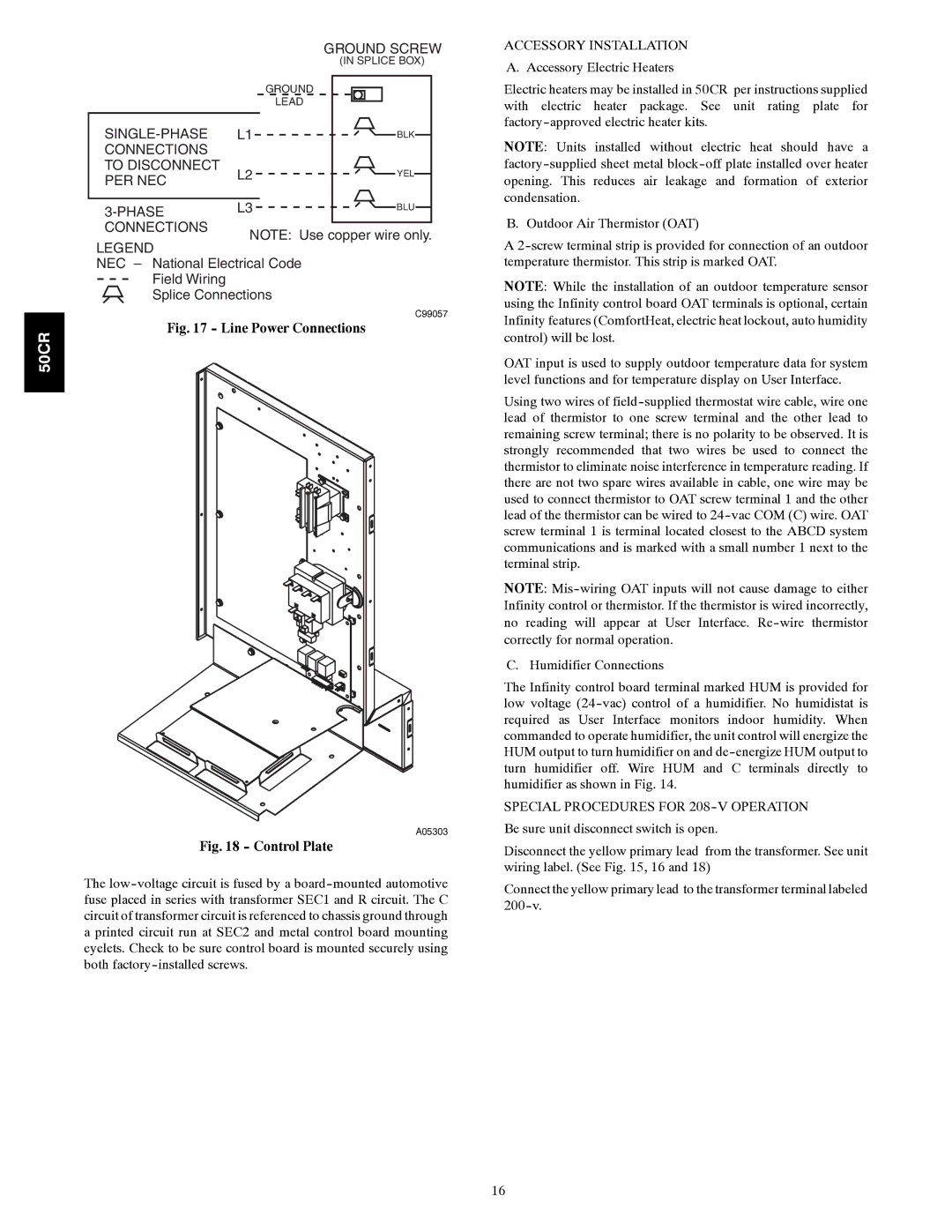
Carrier 50CR installation instructions Line Power Connections, Control Plate

Models: 50CR

1 32
Download 32 pages 7.8 Kb
Page 16
Image 16
Fig. 17 - Line Power Connections


GROUND SCREW


(IN SPLICE BOX)


GROUND


LEAD


SINGLE-PHASE

L1

BLK

CONNECTIONS


TO DISCONNECT

L2

YEL

PER NEC


3-PHASE

L3

BLU


ACCESSORY INSTALLATION

A. Accessory Electric Heaters

Electric heaters may be installed in 50CR per instructions supplied with electric heater package. See unit rating plate for factory-approved electric heater kits.

NOTE: Units installed without electric heat should have a factory-supplied sheet metal block-off plate installed over heater opening. This reduces air leakage and formation of exterior condensation.

CONNECTIONS

LEGEND

NOTE: Use copper wire only.

B. Outdoor Air Thermistor (OAT)

A 2-screw terminal strip is provided for connection of an outdoor

50CR

NEC – National Electrical Code

Field Wiring

Splice Connections

C99057

Fig. 17 - Line Power Connections

A05303

Fig. 18 - Control Plate

The low-voltage circuit is fused by a board-mounted automotive fuse placed in series with transformer SEC1 and R circuit. The C circuit of transformer circuit is referenced to chassis ground through a printed circuit run at SEC2 and metal control board mounting eyelets. Check to be sure control board is mounted securely using both factory-installed screws.

temperature thermistor. This strip is marked OAT.

NOTE: While the installation of an outdoor temperature sensor using the Infinity control board OAT terminals is optional, certain Infinity features (ComfortHeat, electric heat lockout, auto humidity control) will be lost.

OAT input is used to supply outdoor temperature data for system level functions and for temperature display on User Interface.

Using two wires of field-supplied thermostat wire cable, wire one lead of thermistor to one screw terminal and the other lead to remaining screw terminal; there is no polarity to be observed. It is strongly recommended that two wires be used to connect the thermistor to eliminate noise interference in temperature reading. If there are not two spare wires available in cable, one wire may be used to connect thermistor to OAT screw terminal 1 and the other lead of the thermistor can be wired to 24-vac COM (C) wire. OAT screw terminal 1 is terminal located closest to the ABCD system communications and is marked with a small number 1 next to the terminal strip.

NOTE: Mis-wiring OAT inputs will not cause damage to either Infinity control or thermistor. If the thermistor is wired incorrectly, no reading will appear at User Interface. Re-wire thermistor correctly for normal operation.

C. Humidifier Connections

The Infinity control board terminal marked HUM is provided for low voltage (24-vac) control of a humidifier. No humidistat is required as User Interface monitors indoor humidity. When commanded to operate humidifier, the unit control will energize the HUM output to turn humidifier on and de-energize HUM output to turn humidifier off. Wire HUM and C terminals directly to humidifier as shown in Fig. 14.

SPECIAL PROCEDURES FOR 208-V OPERATION Be sure unit disconnect switch is open.

Disconnect the yellow primary lead from the transformer. See unit wiring label. (See Fig. 15, 16 and 18)

Connect the yellow primary lead to the transformer terminal labeled 200-v.

16

Page 16
Image 16
Carrier 50CR installation instructions Line Power Connections, Control Plate