F1 | 5 | STATUS |
| C D | ||
|
|
|
|
|
| B |
HK38EA002 |
|
|
| COMM | 1 | A |
|
|
|
| 1 |
|
|
|
|
|
|
|
| OAT |
|
|
|
| 1 |
|
|
|
|
|
|
|
| R |
|
|
|
|
|
| O Y |
|
|
|
|
|
| W |
|
|
|
|
|
| C |
|
|
|
|
|
| HUM |
HEATER |
|
|
|
|
|
|
1 |
|
|
|
|
|
|
|
|
|
| MOTOR |
|
|
A03169
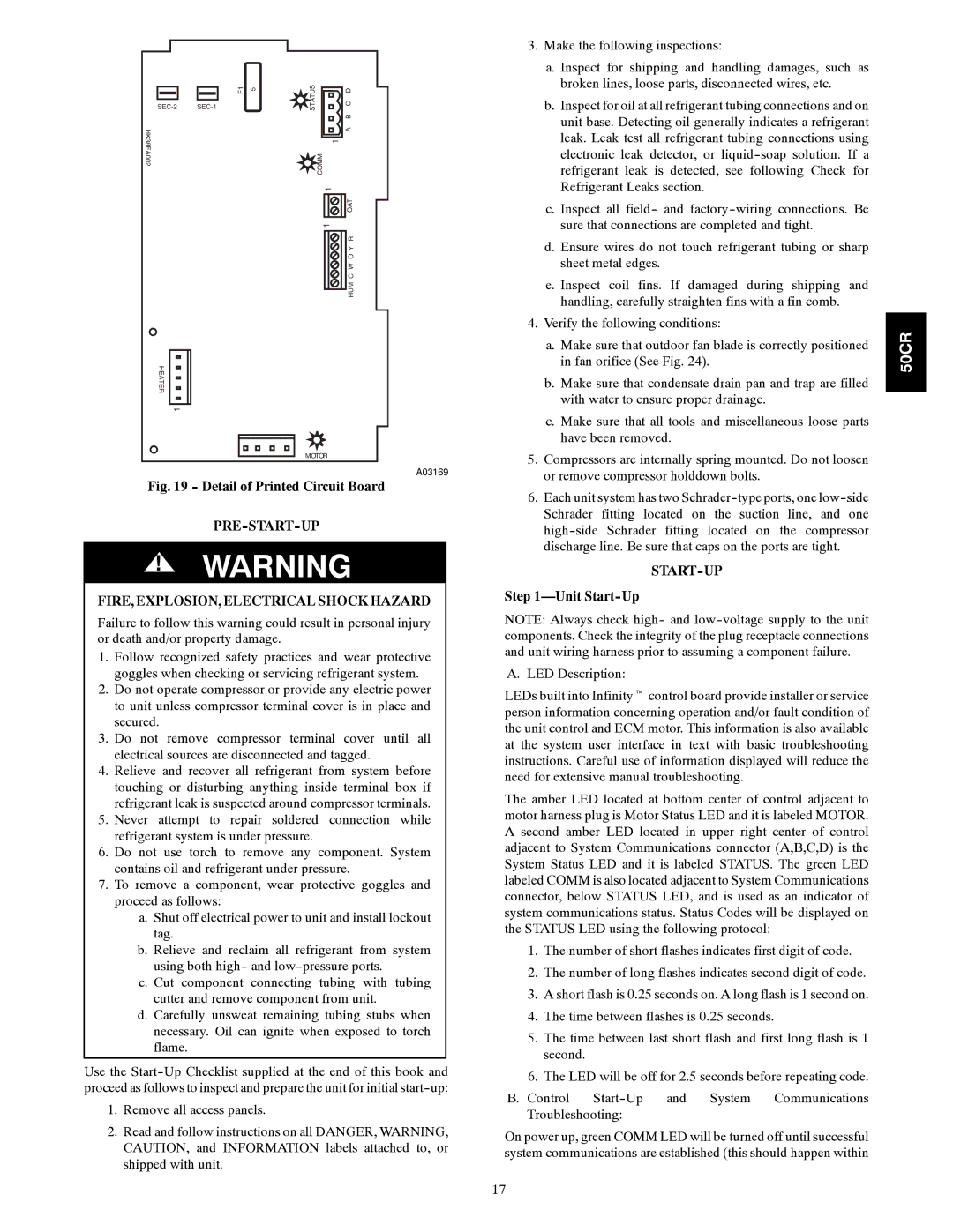
Fig. 19 - Detail of Printed Circuit Board
PRE-START-UP
!WARNING
FIRE, EXPLOSION, ELECTRICAL SHOCK HAZARD
Failure to follow this warning could result in personal injury or death and/or property damage.
1.Follow recognized safety practices and wear protective goggles when checking or servicing refrigerant system.
2.Do not operate compressor or provide any electric power to unit unless compressor terminal cover is in place and secured.
3.Do not remove compressor terminal cover until all electrical sources are disconnected and tagged.
4.Relieve and recover all refrigerant from system before touching or disturbing anything inside terminal box if refrigerant leak is suspected around compressor terminals.
5.Never attempt to repair soldered connection while refrigerant system is under pressure.
6.Do not use torch to remove any component. System contains oil and refrigerant under pressure.
7.To remove a component, wear protective goggles and proceed as follows:
a.Shut off electrical power to unit and install lockout tag.
b.Relieve and reclaim all refrigerant from system using both high- and
c.Cut component connecting tubing with tubing cutter and remove component from unit.
d.Carefully unsweat remaining tubing stubs when necessary. Oil can ignite when exposed to torch flame.
Use the
1.Remove all access panels.
2.Read and follow instructions on all DANGER, WARNING, CAUTION, and INFORMATION labels attached to, or shipped with unit.
3.Make the following inspections:
a.Inspect for shipping and handling damages, such as broken lines, loose parts, disconnected wires, etc.
b.Inspect for oil at all refrigerant tubing connections and on unit base. Detecting oil generally indicates a refrigerant leak. Leak test all refrigerant tubing connections using electronic leak detector, or
c.Inspect all field- and
d.Ensure wires do not touch refrigerant tubing or sharp sheet metal edges.
e.Inspect coil fins. If damaged during shipping and handling, carefully straighten fins with a fin comb.
4.Verify the following conditions:
a.Make sure that outdoor fan blade is correctly positioned in fan orifice (See Fig. 24).
b.Make sure that condensate drain pan and trap are filled with water to ensure proper drainage.
c.Make sure that all tools and miscellaneous loose parts have been removed.
5.Compressors are internally spring mounted. Do not loosen or remove compressor holddown bolts.
6.Each unit system has two
START-UP
Step 1—Unit Start-Up
NOTE: Always check high- and
A. LED Description:
LEDs built into Infinityt control board provide installer or service person information concerning operation and/or fault condition of the unit control and ECM motor. This information is also available at the system user interface in text with basic troubleshooting instructions. Careful use of information displayed will reduce the need for extensive manual troubleshooting.
The amber LED located at bottom center of control adjacent to motor harness plug is Motor Status LED and it is labeled MOTOR. A second amber LED located in upper right center of control adjacent to System Communications connector (A,B,C,D) is the System Status LED and it is labeled STATUS. The green LED labeled COMM is also located adjacent to System Communications connector, below STATUS LED, and is used as an indicator of system communications status. Status Codes will be displayed on the STATUS LED using the following protocol:
1.The number of short flashes indicates first digit of code.
2.The number of long flashes indicates second digit of code.
3.A short flash is 0.25 seconds on. A long flash is 1 second on.
4.The time between flashes is 0.25 seconds.
5.The time between last short flash and first long flash is 1 second.
6.The LED will be off for 2.5 seconds before repeating code.
B.Control
On power up, green COMM LED will be turned off until successful system communications are established (this should happen within
50CR
17