|
| LEGEND |
|
FLA | — | Full Load Amps |
|
LRA | — | Locked Rotor Amps | ® |
MCA | Minimum Circuit Amps |
| |
MOCP — | Maximum Overcurrent Protection |
| |
RLA | — | Rated Load Amps |
|
NO TES: |
|
| |
1. | In compliance with NEC (National Electrical Code) requirements | ||
| for multimotor and combination load equipment (refer to NE C | ||
| Articles 430 and 440), the overcurrent protective device for the | ||
| unit shall | be Power | Supply fuse. The CGA (Canadian Gas |
| Association) units may be fuse or circuit break er. | ||
2. | Minimum wire size is based on 60 C copper wire. I f other than | ||
| 60 C wire | is used, or | if length exceeds wire length in table, |
determine siz e from NEC. .
3.Unbalanced
Never operate a motor where a phase imbalance in supply volt- age is greater than 2%. Use the following formula to determine the percentage of voltage imbalance.
%Voltage imbalance
=100 x max voltage deviation from average voltage average voltage
Heater capacity (kW) based on heater voltage of 208v & 240v.
*If power distibution voltage to unit varies from rated heater voltage, heater kW will vary accordingly.
EXAMPLE: Supply voltage is
AB = 228 v BC = 231 v AC = 227 v
Average Voltage = 228 + 231 + 227 3
= 686 3
= 229
Determine maximum deviation from average voltage. (AB) 229 - 228 = 1 v
(BC) 231 - 229 = 2 v
(AC) 229 - 227 = 2 v Maximum deviation is 2 v.
Determine percent of voltage imbalance.
% Voltage Imbalance = 100 x |
| 2 | |
229 | |||
| |||
= 0.8% |
|
| |
This amount of phase imbalance is satisfactory as it is below the maximum allowable 2%.
IMPORTANT: If the supply voltage phase imbalance is more than 2%, contact your local electric utility company immediately.
C03014
50CR
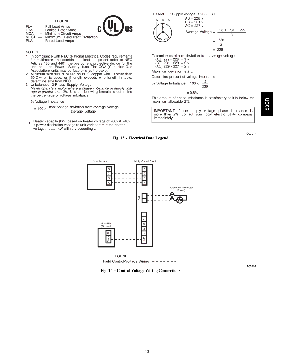
Fig. 13 - Electrical Data Legend
User Interface
D
C
B
A
Humidifier (Optional)
24vac C
Infinity Control Board
D
C
B
A
Outdoor Air Thermistor
(if used)
OAT
HUM C W O Y R
LEGEND
Field
A05302
Fig. 14 - Control Voltage Wiring Connections
13