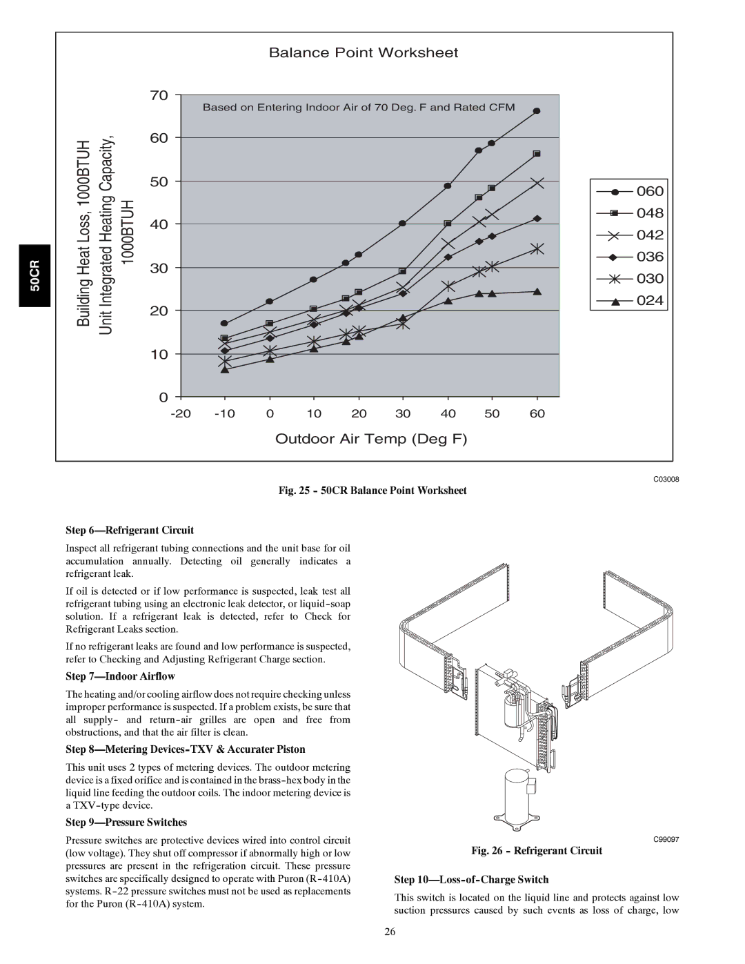
Balance Point Worksheet
50CR
|
|
| 70 | Based on Entering Indoor Air of 70 Deg. F and Rated CFM |
| ||||||
|
|
|
|
| |||||||
Building Heat Loss, 1000BTUH | Unit Integrated Heating Capacity, |
| 60 |
|
|
|
|
|
|
|
|
| 50 |
|
|
|
|
|
|
|
| ||
1000BTUH | 40 |
|
|
|
|
|
|
|
| ||
30 |
|
|
|
|
|
|
|
| |||
20 |
|
|
|
|
|
|
|
| |||
|
|
|
|
|
|
|
|
| |||
|
|
| 10 |
|
|
|
|
|
|
|
|
|
|
| 0 |
|
|
|
|
|
|
|
|
|
|
| 0 | 10 | 20 | 30 | 40 | 50 | 60 | ||
Outdoor Air Temp (Deg F)
060
![]()
![]() 048
048
042
036
![]() 030
030
024
C03008
Fig. 25 - 50CR Balance Point Worksheet
Step 6—Refrigerant Circuit
Inspect all refrigerant tubing connections and the unit base for oil accumulation annually. Detecting oil generally indicates a refrigerant leak.
If oil is detected or if low performance is suspected, leak test all refrigerant tubing using an electronic leak detector, or
If no refrigerant leaks are found and low performance is suspected, refer to Checking and Adjusting Refrigerant Charge section.
Step 7—Indoor Airflow
The heating and/or cooling airflow does not require checking unless improper performance is suspected. If a problem exists, be sure that all supply- and
Step 8—Metering Devices-TXV & Accurater Piston
This unit uses 2 types of metering devices. The outdoor metering device is a fixed orifice and is contained in the
Step 9—Pressure Switches
Pressure switches are protective devices wired into control circuit (low voltage). They shut off compressor if abnormally high or low pressures are present in the refrigeration circuit. These pressure switches are specifically designed to operate with Puron
C99097
Fig. 26 - Refrigerant Circuit
Step 10—Loss-of-Charge Switch
This switch is located on the liquid line and protects against low suction pressures caused by such events as loss of charge, low
26