Step 14—System Information
LOSS-OF-CHARGE SWITCH
The loss of charge switch is a protective device wired into control circuit (low voltage). It shuts off the compressor if abnormally low pressures are present in the refrigeration circuit.
NOTE: Because these switches are attached to refrigeration system under pressure, it is not advisable to remove this device for troubleshooting unless you are reasonably certain that a problem exists. If switch must be removed, remove and recover all system charge so that pressure gauges read 0 psi. Never open system without breaking vacuum with dry nitrogen.
CHECK DEFROST THERMOSTAT
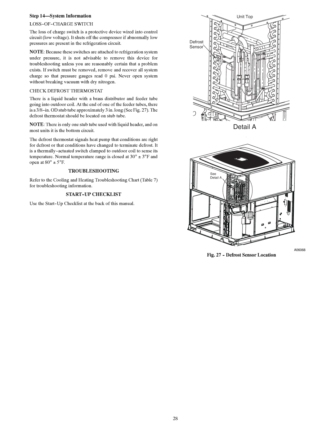
There is a liquid header with a brass distributor and feeder tube going into outdoor coil. At the end of one of the feeder tubes, there is a
NOTE: There is only one stub tube used with liquid header, and on most units it is the bottom circuit.
The defrost thermostat signals heat pump that conditions are right for defrost or that conditions have changed to terminate defrost. It is a
TROUBLESHOOTING
Refer to the Cooling and Heating Troubleshooting Chart (Table 7) for troubleshooting information.
START-UP CHECKLIST
Use the
Unit Top
Defrost
Sensor
Detail A
See
Detail A
A06068
Fig. 27 - Defrost Sensor Location
28