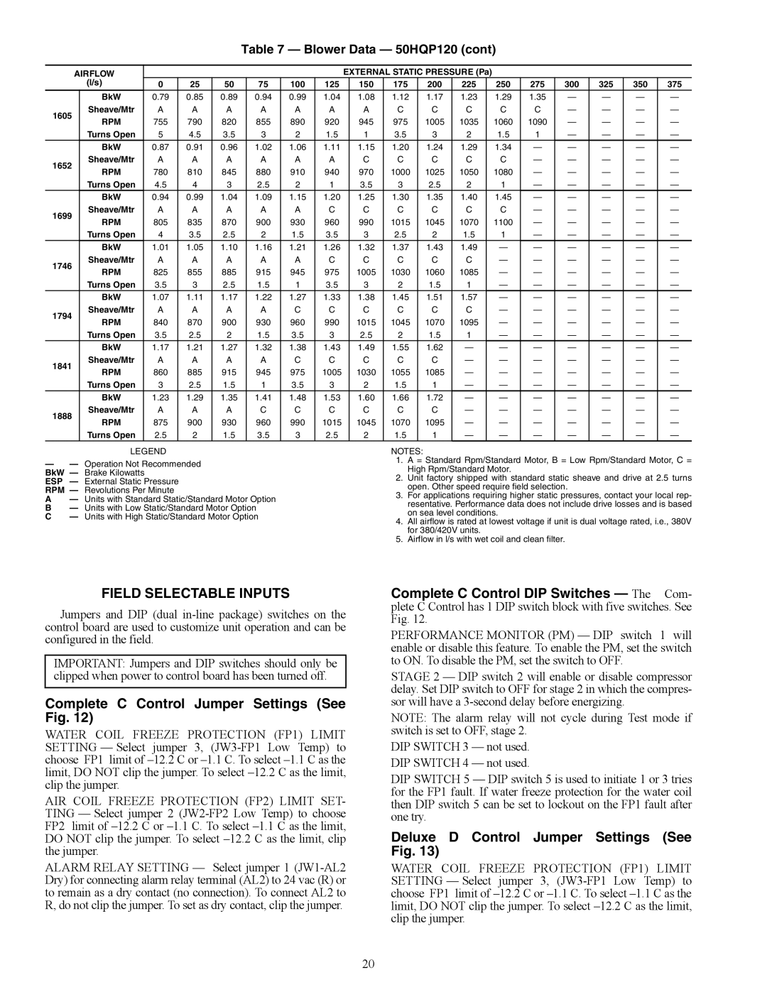
Table 7 — Blower Data — 50HQP120 (cont)
AIRFLOW |
|
|
|
|
|
| EXTERNAL STATIC PRESSURE (Pa) |
|
|
|
|
|
| ||||||
| (l/s) | 0 | 25 | 50 | 75 | 100 | 125 |
| 150 | 175 | 200 | 225 |
| 250 | 275 | 300 | 325 | 350 | 375 |
| BkW | 0.79 | 0.85 | 0.89 | 0.94 | 0.99 | 1.04 |
| 1.08 | 1.12 | 1.17 | 1.23 |
| 1.29 | 1.35 | — | — | — | — |
1605 | Sheave/Mtr | A | A | A | A | A | A |
| A | C | C | C |
| C | C | — | — | — | — |
RPM | 755 | 790 | 820 | 855 | 890 | 920 |
| 945 | 975 | 1005 | 1035 |
| 1060 | 1090 | — | — | — | — | |
|
|
| |||||||||||||||||
| Turns Open | 5 | 4.5 | 3.5 | 3 | 2 | 1.5 |
| 1 | 3.5 | 3 | 2 |
| 1.5 | 1 | — | — | — | — |
| BkW | 0.87 | 0.91 | 0.96 | 1.02 | 1.06 | 1.11 |
| 1.15 | 1.20 | 1.24 | 1.29 |
| 1.34 | — | — | — | — | — |
1652 | Sheave/Mtr | A | A | A | A | A | A |
| C | C | C | C |
| C | — | — | — | — | — |
RPM | 780 | 810 | 845 | 880 | 910 | 940 |
| 970 | 1000 | 1025 | 1050 |
| 1080 | — | — | — | — | — | |
|
|
| |||||||||||||||||
| Turns Open | 4.5 | 4 | 3 | 2.5 | 2 | 1 |
| 3.5 | 3 | 2.5 | 2 |
| 1 | — | — | — | — | — |
| BkW | 0.94 | 0.99 | 1.04 | 1.09 | 1.15 | 1.20 |
| 1.25 | 1.30 | 1.35 | 1.40 |
| 1.45 | — | — | — | — | — |
1699 | Sheave/Mtr | A | A | A | A | A | C |
| C | C | C | C |
| C | — | — | — | — | — |
RPM | 805 | 835 | 870 | 900 | 930 | 960 |
| 990 | 1015 | 1045 | 1070 |
| 1100 | — | — | — | — | — | |
|
|
| |||||||||||||||||
| Turns Open | 4 | 3.5 | 2.5 | 2 | 1.5 | 3.5 |
| 3 | 2.5 | 2 | 1.5 |
| 1 | — | — | — | — | — |
| BkW | 1.01 | 1.05 | 1.10 | 1.16 | 1.21 | 1.26 |
| 1.32 | 1.37 | 1.43 | 1.49 |
| — | — | — | — | — | — |
1746 | Sheave/Mtr | A | A | A | A | A | C |
| C | C | C | C |
| — | — | — | — | — | — |
RPM | 825 | 855 | 885 | 915 | 945 | 975 |
| 1005 | 1030 | 1060 | 1085 |
| — | — | — | — | — | — | |
|
|
| |||||||||||||||||
| Turns Open | 3.5 | 3 | 2.5 | 1.5 | 1 | 3.5 |
| 3 | 2 | 1.5 | 1 |
| — | — | — | — | — | — |
| BkW | 1.07 | 1.11 | 1.17 | 1.22 | 1.27 | 1.33 |
| 1.38 | 1.45 | 1.51 | 1.57 |
| — | — | — | — | — | — |
1794 | Sheave/Mtr | A | A | A | A | C | C |
| C | C | C | C |
| — | — | — | — | — | — |
RPM | 840 | 870 | 900 | 930 | 960 | 990 |
| 1015 | 1045 | 1070 | 1095 |
| — | — | — | — | — | — | |
|
|
| |||||||||||||||||
| Turns Open | 3.5 | 2.5 | 2 | 1.5 | 3.5 | 3 |
| 2.5 | 2 | 1.5 | 1 |
| — | — | — | — | — | — |
| BkW | 1.17 | 1.21 | 1.27 | 1.32 | 1.38 | 1.43 |
| 1.49 | 1.55 | 1.62 | — |
| — | — | — | — | — | — |
1841 | Sheave/Mtr | A | A | A | A | C | C |
| C | C | C | — |
| — | — | — | — | — | — |
RPM | 860 | 885 | 915 | 945 | 975 | 1005 |
| 1030 | 1055 | 1085 | — |
| — | — | — | — | — | — | |
|
|
| |||||||||||||||||
| Turns Open | 3 | 2.5 | 1.5 | 1 | 3.5 | 3 |
| 2 | 1.5 | 1 | — |
| — | — | — | — | — | — |
| BkW | 1.23 | 1.29 | 1.35 | 1.41 | 1.48 | 1.53 |
| 1.60 | 1.66 | 1.72 | — |
| — | — | — | — | — | — |
1888 | Sheave/Mtr | A | A | A | C | C | C |
| C | C | C | — |
| — | — | — | — | — | — |
RPM | 875 | 900 | 930 | 960 | 990 | 1015 |
| 1045 | 1070 | 1095 | — |
| — | — | — | — | — | — | |
|
|
| |||||||||||||||||
| Turns Open | 2.5 | 2 | 1.5 | 3.5 | 3 | 2.5 |
| 2 | 1.5 | 1 | — |
| — | — | — | — | — | — |
LEGEND
—— Operation Not Recommended BkW — Brake Kilowatts
ESP — External Static Pressure RPM — Revolutions Per Minute
A — Units with Standard Static/Standard Motor Option B — Units with Low Static/Standard Motor Option
C — Units with High Static/Standard Motor Option
NOTES:
1.A = Standard Rpm/Standard Motor, B = Low Rpm/Standard Motor, C = High Rpm/Standard Motor.
2.Unit factory shipped with standard static sheave and drive at 2.5 turns open. Other speed require field selection.
3.For applications requiring higher static pressures, contact your local rep- resentative. Performance data does not include drive losses and is based on sea level conditions.
4.All airflow is rated at lowest voltage if unit is dual voltage rated, i.e., 380V for 380/420V units.
5.Airflow in l/s with wet coil and clean filter.
FIELD SELECTABLE INPUTS
Jumpers and DIP (dual
IMPORTANT: Jumpers and DIP switches should only be clipped when power to control board has been turned off.
Complete C Control Jumper Settings (See Fig. 12)
WATER COIL FREEZE PROTECTION (FP1) LIMIT SETTING — Select jumper 3,
AIR COIL FREEZE PROTECTION (FP2) LIMIT SET- TING — Select jumper 2
ALARM RELAY SETTING — Select jumper 1
Complete C Control DIP Switches — The Com- plete C Control has 1 DIP switch block with five switches. See Fig. 12.
PERFORMANCE MONITOR (PM) — DIP switch 1 will enable or disable this feature. To enable the PM, set the switch to ON. To disable the PM, set the switch to OFF.
STAGE 2 — DIP switch 2 will enable or disable compressor delay. Set DIP switch to OFF for stage 2 in which the compres- sor will have a
NOTE: The alarm relay will not cycle during Test mode if switch is set to OFF, stage 2.
DIP SWITCH 3 — not used. DIP SWITCH 4 — not used.
DIP SWITCH 5 — DIP switch 5 is used to initiate 1 or 3 tries for the FP1 fault. If water freeze protection for the water coil then DIP switch 5 can be set to lockout on the FP1 fault after one try.
Deluxe D Control Jumper Settings (See Fig. 13)
WATER COIL FREEZE PROTECTION (FP1) LIMIT SETTING — Select jumper 3,
20