LEFT RETURN STRAIGHT DISCHARGE | RIGHT RETURN STRAIGHT DISCHARGE |
CAP![]()
CAP
FRONT
B
O ![]()
![]()
![]()
![]()
![]()
CBP
PQR
K
|
| A | BSP | BSP |
|
|
|
| |
|
|
|
| C |
| F |
| D |
|
|
|
|
| |
EAP | G |
| E |
|
|
|
|
|
![]()
![]() M
M
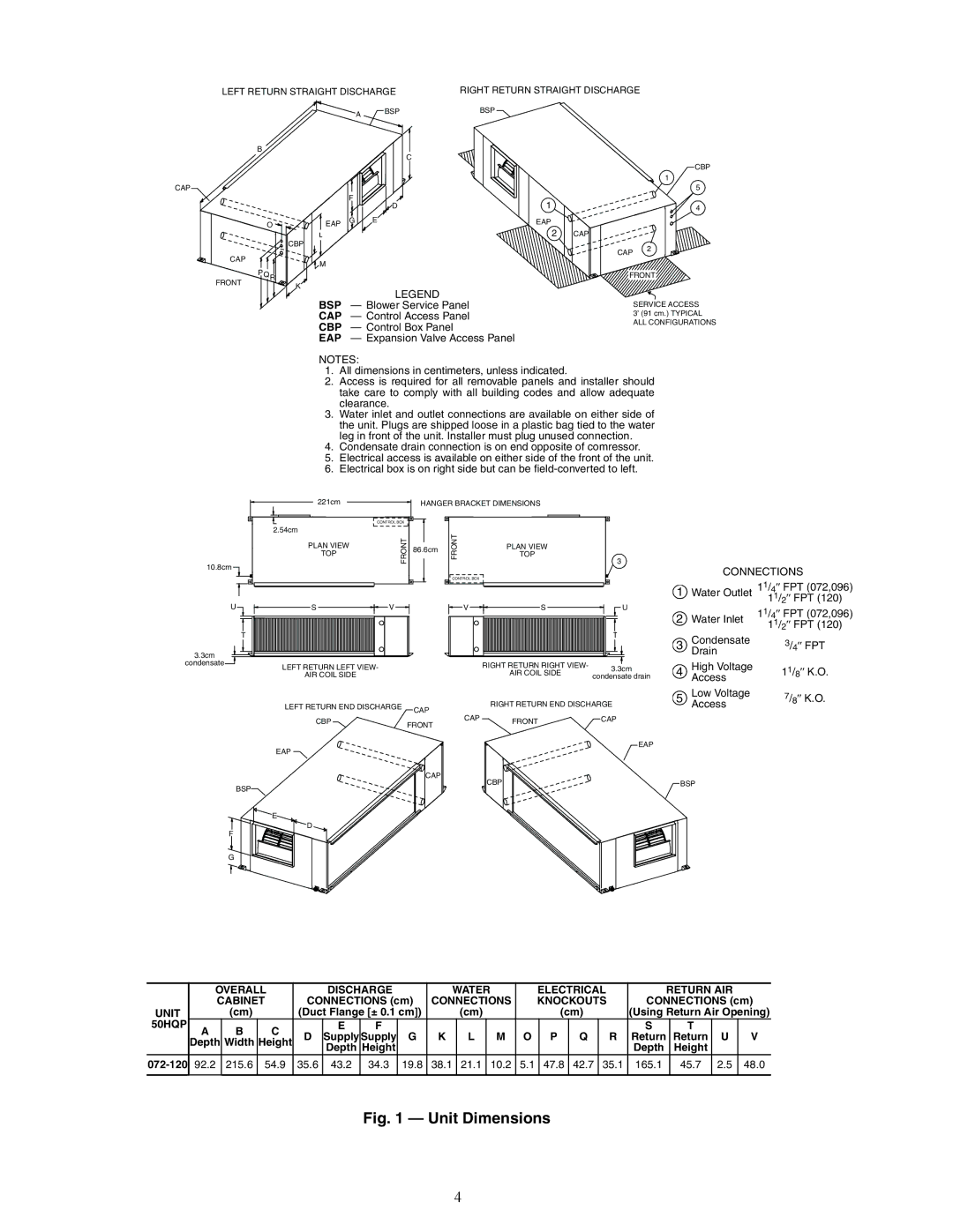
LEGEND
BSP — Blower Service Panel
CAP — Control Access Panel
CBP — Control Box Panel
EAP — Expansion Valve Access Panel
1 ![]()
EAP
2
CBP
1
5
4
CAP
CAP 2
![]()
![]()
![]()
![]()
![]() FRONT
FRONT ![]()
![]()
SERVICE ACCESS
3’ (91 cm.) TYPICAL ALL CONFIGURATIONS
NOTES:
1.All dimensions in centimeters, unless indicated.
2.Access is required for all removable panels and installer should take care to comply with all building codes and allow adequate clearance.
3.Water inlet and outlet connections are available on either side of the unit. Plugs are shipped loose in a plastic bag tied to the water leg in front of the unit. Installer must plug unused connection.
4.Condensate drain connection is on end opposite of comressor.
5.Electrical access is available on either side of the front of the unit.
6.Electrical box is on right side but can be
221cm
HANGER BRACKET DIMENSIONS
|
| CONTROL BOX |
|
| 2.54cm | FRONT |
|
| PLAN VIEW | 86.6cm | |
| TOP |
| |
|
|
| |
10.8cm |
|
|
|
U | S | V |
|
| T |
|
|
3.3cm |
|
|
|
condensate | LEFT RETURN LEFT VIEW- |
| |
|
| ||
| AIR COIL SIDE |
|
|
| LEFT RETURN END DISCHARGE | CAP | |
|
|
| |
| CBP |
| FRONT |
|
|
| |
| EAP |
|
|
|
|
| CAP |
| BSP |
|
|
| E |
|
|
F | D |
|
|
|
|
| |
FRONT | PLAN VIEW |
| TOP |
| 3 |
CONTROL BOX |
|
|
| CONNECTIONS | |
|
|
|
| 11/4″ FPT (072,096) | |
|
|
| 1 | Water Outlet | |
V | S | U |
|
| 11/2″ FPT (120) |
2 |
| 11/4″ FPT (072,096) | |||
|
|
| Water Inlet | ||
|
|
| 11/2″ FPT (120) | ||
|
|
| 3 | DrainCondensate | 3/4″ FPT |
| RIGHT RETURN RIGHT VIEW- | 3.3cm | 4 | High Voltage | 1 |
| AIR COIL SIDE | condensate drain | Access | 1 /8″ K.O. | |
| RIGHT RETURN END DISCHARGE | 5 | Low Voltage | 7/8″ K.O. | |
|
| Access |
| ||
CAP | FRONT | CAP |
|
| EAP |
| CBP | BSP |
G
a50-8531
| OVERALL |
| DISCHARGE |
| WATER |
|
| ELECTRICAL |
| RETURN AIR |
| |||||||||||
|
| CABINET | CONNECTIONS (cm) | CONNECTIONS |
| KNOCKOUTS | CONNECTIONS (cm) | |||||||||||||||
UNIT |
|
| (cm) |
| (Duct Flange [± 0.1 cm]) |
| (cm) |
|
|
| (cm) |
| (Using Return Air Opening) | |||||||||
50HQP | A |
| B | C |
| E | F |
|
|
|
|
|
|
|
|
|
| S |
| T |
|
|
|
| D | Supply | Supply | G | K | L |
| M | O |
| P | Q | R | Return | Return | U | V | ||||
| Depth | Width | Height |
|
| |||||||||||||||||
|
|
|
|
|
| Depth | Height |
|
|
|
|
|
|
|
|
|
| Depth |
| Height |
|
|
92.2 |
| 215.6 | 54.9 | 35.6 | 43.2 | 34.3 | 19.8 | 38.1 | 21.1 |
| 10.2 | 5.1 |
| 47.8 | 42.7 | 35.1 | 165.1 |
| 45.7 | 2.5 | 48.0 | |
|
|
|
|
|
|
|
|
|
|
|
|
|
|
|
|
|
|
|
|
|
|
|
Fig. 1 — Unit Dimensions
4