immediately once the demand is removed. The control re- verts to Heating Stage 1 mode. If there is a master/slave or dual compressor application, all compressor relays and re- lated functions will operate per their associated DIP switch 2 setting on S1.
HEATING STAGE 3 — In Heating Stage 3 mode, the Fan Enable, Fan Speed and Compressor relays remain on. The EH1 output is turned on immediately. With continuing Heat Stage 3 demand, EH2 will turn on after 10 minutes. EH1 and EH2 are turned off immediately when the Heating Stage 3 demand is removed. The control reverts to Heating Stage 2 mode.
Output EH2 will be off if FP1 is greater than 7.2 C AND FP2 (when shorted) is greater than 43.3 C during Heating Stage 3 mode. This condition will have a
EMERGENCY HEAT — In Emergency Heat mode, the Fan Enable and Fan Speed relays are turned on. The EH1 output is turned on immediately. With continuing Emergen- cy Heat demand, EH2 will turn on after 5 minutes. Fan En- able and Fan Speed relays are turned off after a
Output EH1, EH2, Fan Enable, and Fan Speed will be ON if the G input is not active during Emergency Heat mode.
COOLING STAGE 1 — In Cooling Stage 1 mode, the Fan Enable, compressor and RV relays are turned on immediate- ly. If configured as stage 2 (DIP switch set to OFF) then the compressor and fan will not turn on until there is a stage 2 demand. The Fan Enable and compressor relays are turned off immediately when the Cooling Stage 1 demand is re- moved. The control reverts to Standby mode. The RV relay remains on until there is a heating demand. If there is a mas- ter/slave or dual compressor application, all compressor re- lays and related functions will track with their associated DIP switch 2 on S1.
COOLING STAGE 2 — In Cooling Stage 2 mode, the Fan Enable, compressor and RV relays remain on. The Fan Speed relay is turned on immediately and turned off once the Cooling Stage 2 demand is removed. The control reverts to Cooling Stage 1 mode. If there is a master/slave or dual compressor application, all compressor relays and related functions will track with their associated DIP switch 2 on S1.
NIGHT LOW LIMIT (NLL) STAGED HEATING — In NLL staged Heating mode, the override (OVR) input be- comes active and is recognized as a call for heating and the control will immediately go into a Heating Stage 1 mode. With an additional 30 minutes of NLL demand, the control will go into Heating Stage 2 mode. With another additional 30 minutes of NLL demand, the control will go into Heating Stage 3 mode.
SYSTEM TEST
System testing provides the ability to check the control operation. The control enters a
Test Mode — To enter Test mode on Complete C or De- luxe D controls, cycle the fan 3 times within 60 seconds. The LED
also power on and off during Test mode. See Tables
NOTE: The Deluxe D control has a flashing code and alarm relay cycling code that will both have the same numerical label. For example, flashing code 1 will have an alarm relay cycling code 1. Code 1 indicates the control has not faulted since the last power off to power on sequence.
Retry Mode — In Retry mode, the status LED will start to flash slowly to signal that the control is trying to recover from an input fault. The control will stage off the outputs and try to again satisfy the thermostat used to terminal Y. Once the ther- mostat input calls are satisfied, the control will continue normal operation.
NOTE: If 3 consecutive faults occur without satisfying the thermostat input call to terminal Y, the control will go into lockout mode. The last fault causing the lockout is stored in memory and can be viewed by entering Test mode.
Aquazone™ Deluxe D Control LED Indica-
tors — There are 3 LED indicators on the Deluxe D control: STATUS LED — Status LED indicates the current status or mode of the Deluxe D control. The Status LED light is green.
TEST LED — Test LED will be activated any time the De- luxe D control is in Test mode. The Test LED light is yellow.
FAULT LED — Fault LED light is red. The fault LED will always flash a code representing the last fault in memory. If there is no fault in memory, the fault LED will flash code 1 on the and appear as 1 fast flash alternating with a
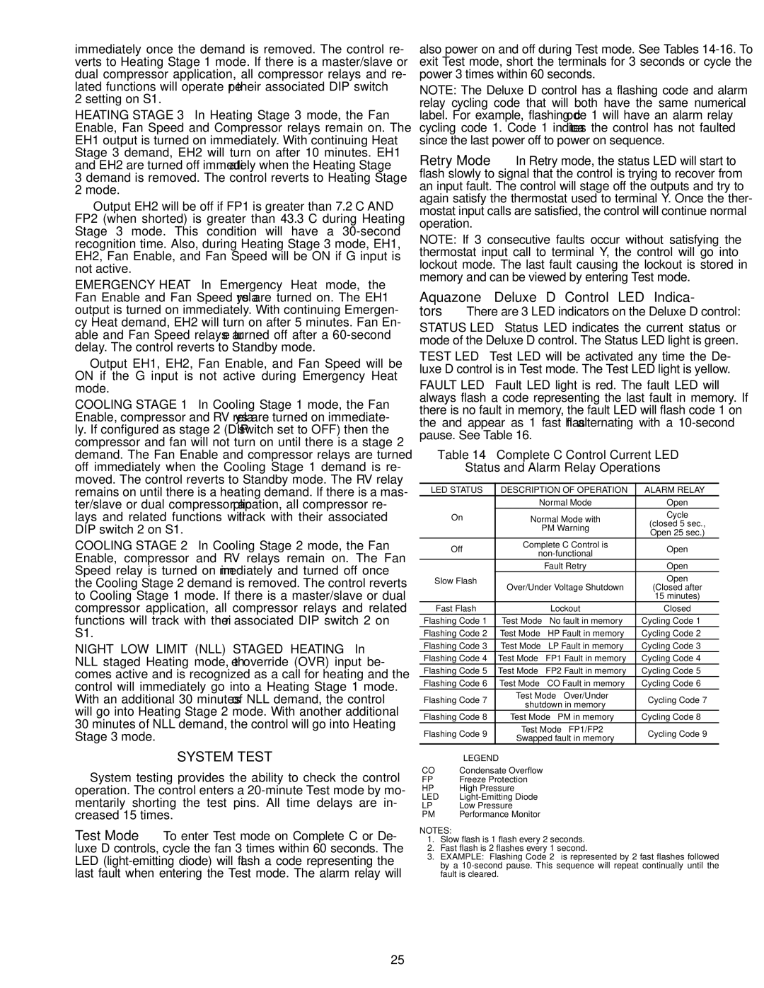
Table 14 — Complete C Control Current LED
Status and Alarm Relay Operations
LED STATUS |
| DESCRIPTION OF OPERATION | ALARM RELAY | |
|
|
| Normal Mode | Open |
| On |
| Normal Mode with | Cycle |
|
|
| PM Warning | (closed 5 sec., |
|
|
| Open 25 sec.) | |
|
|
|
| |
| Off |
| Complete C Control is | Open |
|
| |||
|
|
|
| |
|
|
| Fault Retry | Open |
Slow Flash |
| Over/Under Voltage Shutdown | Open | |
|
|
| (Closed after | |
|
|
|
| 15 minutes) |
| Fast Flash |
| Lockout | Closed |
Flashing Code 1 | Test Mode — No fault in memory | Cycling Code 1 | ||
Flashing Code 2 | Test Mode — HP Fault in memory | Cycling Code 2 | ||
Flashing Code 3 | Test Mode — LP Fault in memory | Cycling Code 3 | ||
Flashing Code 4 | Test Mode — FP1 Fault in memory | Cycling Code 4 | ||
Flashing Code 5 | Test Mode — FP2 Fault in memory | Cycling Code 5 | ||
Flashing Code 6 | Test Mode — CO Fault in memory | Cycling Code 6 | ||
Flashing Code 7 |
| Test Mode — Over/Under | Cycling Code 7 | |
| shutdown in memory | |||
|
|
|
| |
Flashing Code 8 |
| Test Mode — PM in memory | Cycling Code 8 | |
Flashing Code 9 |
| Test Mode — FP1/FP2 | Cycling Code 9 | |
| Swapped fault in memory | |||
|
|
|
| |
| LEGEND |
|
| |
CO | — Condensate Overflow |
| ||
FP | — Freeze Protection |
| ||
HP | — High Pressure |
| ||
LED — |
| |||
LP | — Low Pressure |
| ||
PM | — Performance Monitor |
| ||
NOTES:
1.Slow flash is 1 flash every 2 seconds.
2.Fast flash is 2 flashes every 1 second.
3.EXAMPLE: “Flashing Code 2” is represented by 2 fast flashes followed by a
25