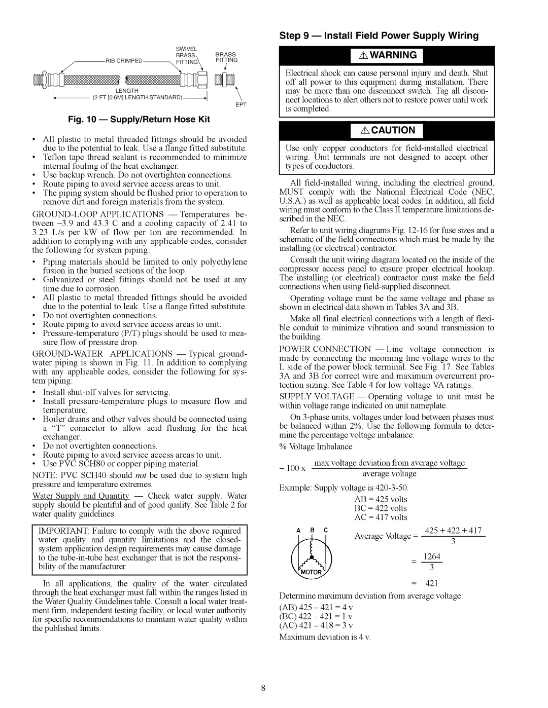
| SWIVEL |
| BRASS | ||
| BRASS |
| |||
RIB CRIMPED | FITTING |
| FITTING | ||
|
|
|
|
|
|
|
|
|
|
|
|
|
|
|
|
|
|
LENGTH
![]() (2 FT [0.6M] LENGTH STANDARD)
(2 FT [0.6M] LENGTH STANDARD) ![]()
EPT
Fig. 10 — Supply/Return Hose Kit
•All plastic to metal threaded fittings should be avoided due to the potential to leak. Use a flange fitted substitute.
•Teflon tape thread sealant is recommended to minimize internal fouling of the heat exchanger.
•Use backup wrench. Do not overtighten connections.
•Route piping to avoid service access areas to unit.
•The piping system should be flushed prior to operation to remove dirt and foreign materials from the system.
3.23L/s per kW of flow per ton are recommended. In addition to complying with any applicable codes, consider the following for system piping:
•Piping materials should be limited to only polyethylene fusion in the buried sections of the loop.
•Galvanized or steel fittings should not be used at any time due to corrosion.
•All plastic to metal threaded fittings should be avoided due to the potential to leak. Use a flange fitted substitute.
•Do not overtighten connections.
•Route piping to avoid service access areas to unit.
•
•Install
•Install
•Boiler drains and other valves should be connected using a “T” connector to allow acid flushing for the heat exchanger.
•Do not overtighten connections.
•Route piping to avoid service access areas to unit.
•Use PVC SCH80 or copper piping material.
NOTE: PVC SCH40 should not be used due to system high pressure and temperature extremes.
Water Supply and Quantity — Check water supply. Water supply should be plentiful and of good quality. See Table 2 for water quality guidelines.
IMPORTANT: Failure to comply with the above required water quality and quantity limitations and the closed- system application design requirements may cause damage to the
In all applications, the quality of the water circulated through the heat exchanger must fall within the ranges listed in the Water Quality Guidelines table. Consult a local water treat- ment firm, independent testing facility, or local water authority for specific recommendations to maintain water quality within the published limits.
Step 9 — Install Field Power Supply Wiring
![]() WARNING
WARNING
Electrical shock can cause personal injury and death. Shut off all power to this equipment during installation. There may be more than one disconnect switch. Tag all discon- nect locations to alert others not to restore power until work is completed.
![]() CAUTION
CAUTION
Use only copper conductors for
All
Refer to unit wiring diagrams Fig.
Consult the unit wiring diagram located on the inside of the compressor access panel to ensure proper electrical hookup. The installing (or electrical) contractor must make the field connections when using
Operating voltage must be the same voltage and phase as shown in electrical data shown in Tables 3A and 3B.
Make all final electrical connections with a length of flexi- ble conduit to minimize vibration and sound transmission to the building.
POWER CONNECTION — Line voltage connection is made by connecting the incoming line voltage wires to the L side of the power block terminal. See Fig. 17. See Tables 3A and 3B for correct wire and maximum overcurrent pro- tection sizing. See Table 4 for low voltage VA ratings.
SUPPLY VOLTAGE — Operating voltage to unit must be within voltage range indicated on unit nameplate.
On
% Voltage Imbalance
= 100 x | max voltage deviation from average voltage | ||
| average voltage |
|
|
Example: Supply voltage is |
|
| |
| AB = 425 volts |
|
|
| BC = 422 volts |
|
|
| AC = 417 volts |
|
|
| Average Voltage = | 425 + 422 + 417 | |
| 3 |
| |
|
|
| |
| = | 1264 |
|
|
| 3 |
|
= 421
Determine maximum deviation from average voltage:
(AB) 425 – 421 = 4 v (BC) 422 – 421 = 1 v (AC) 421 – 418 = 3 v
Maximum deviation is 4 v.
8