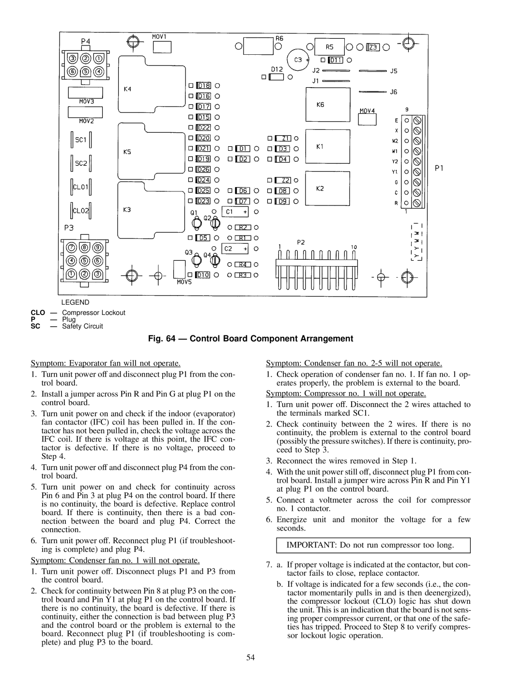
LEGEND

CLO Ð Compressor Lockout

PÐ Plug

SC Ð Safety Circuit

Fig. 64 Ð Control Board Component Arrangement

Symptom: Evaporator fan will not operate.

1.Turn unit power off and disconnect plug P1 from the con- trol board.

2.Install a jumper across Pin R and Pin G at plug P1 on the control board.

3.Turn unit power on and check if the indoor (evaporator) fan contactor (IFC) coil has been pulled in. If the con- tactor has not been pulled in, check the voltage across the IFC coil. If there is voltage at this point, the IFC con- tactor is defective. If there is no voltage, proceed to Step 4.

4.Turn unit power off and disconnect plug P4 from the con- trol board.

5.Turn unit power on and check for continuity across Pin 6 and Pin 3 at plug P4 on the control board. If there is no continuity, the board is defective. Replace control board. If there is continuity, then there is a bad con- nection between the board and plug P4. Correct the connection.

6.Turn unit power off. Reconnect plug P1 (if troubleshoot- ing is complete) and plug P4.

Symptom: Condenser fan no. 1 will not operate.

1.Turn unit power off. Disconnect plugs P1 and P3 from the control board.

2.Check for continuity between Pin 8 at plug P3 on the con- trol board and Pin Y1 at plug P1 on the control board. If there is no continuity, the board is defective. If there is continuity, either the connection is bad between plug P3 and the control board or the problem is external to the board. Reconnect plug P1 (if troubleshooting is com- plete) and plug P3 to the board.

Symptom: Condenser fan no. 2-5 will not operate.

1.Check operation of condenser fan no. 1. If fan no. 1 op- erates properly, the problem is external to the board.

Symptom: Compressor no. 1 will not operate.

1.Turn unit power off. Disconnect the 2 wires attached to the terminals marked SC1.

2.Check continuity between the 2 wires. If there is no continuity, the problem is external to the control board (possibly the pressure switches). If there is continuity, pro- ceed to Step 3.

3.Reconnect the wires removed in Step 1.

4.With the unit power still off, disconnect plug P1 from con- trol board. Install a jumper wire across Pin R and Pin Y1 at plug P1 on the control board.

5.Connect a voltmeter across the coil for compressor no. 1 contactor.

6.Energize unit and monitor the voltage for a few seconds.

IMPORTANT: Do not run compressor too long.

7.a. If proper voltage is indicated at the contactor, but con- tactor fails to close, replace contactor.

b.If voltage is indicated for a few seconds (i.e., the con- tactor momentarily pulls in and is then deenergized), the compressor lockout (CLO) logic has shut down the unit. This is an indication that the board is not sens- ing proper compressor current, or that one of the safe- ties has tripped. Proceed to Step 8 to verify compres- sor lockout logic operation.

54

Page 54
Image 54
Carrier NP034-074 specifications Control Board Component Arrangement

NP034-074 specifications

The Carrier NP034-074 is an advanced rooftop unit designed for commercial heating, ventilation, and air conditioning (HVAC) applications. This unit is part of Carrier’s extensive range of rooftop units that are known for their energy efficiency, reliability, and innovative features. The NP034-074 series is particularly recognized for its robust performance in diverse environmental conditions, making it ideal for a variety of commercial building types.

One of the standout features of the NP034-074 is its high-efficiency compressor. Equipped with a scroll compressor, the unit offers enhanced performance and quieter operation compared to traditional reciprocating compressors. This design not only improves energy efficiency but also reduces operating costs over time. The unit is designed to meet or exceed the latest efficiency standards, ensuring that businesses can enjoy optimal indoor comfort while keeping energy consumption low.

The NP034-074 also integrates advanced control technologies that provide users with greater flexibility and ease of operation. The intuitive control system allows for precise temperature management and can be easily integrated with building automation systems. This enables users to monitor and adjust settings remotely, ensuring consistent and efficient climate control throughout the facility.

Another key characteristic of the NP034-074 is its robust construction. Built to withstand various weather conditions, the unit features a galvanized steel cabinet with a powder-coated finish for corrosion resistance. Its design also facilitates easy access for maintenance and service, which minimizes downtime and operational interruptions.

In terms of air distribution, the NP034-074 incorporates a powerful blower system that ensures even and effective airflow throughout the space. This design improves indoor air quality by enhancing ventilation while maintaining comfort levels. Additionally, the unit can be customized with options such as economizers and variable speed fans to optimize performance based on specific building needs.

The NP034-074 is a versatile and reliable choice for businesses looking to enhance their HVAC systems. With its combination of energy efficiency, advanced technology, and robust construction, this rooftop unit stands out as a top choice for commercial climate control solutions.