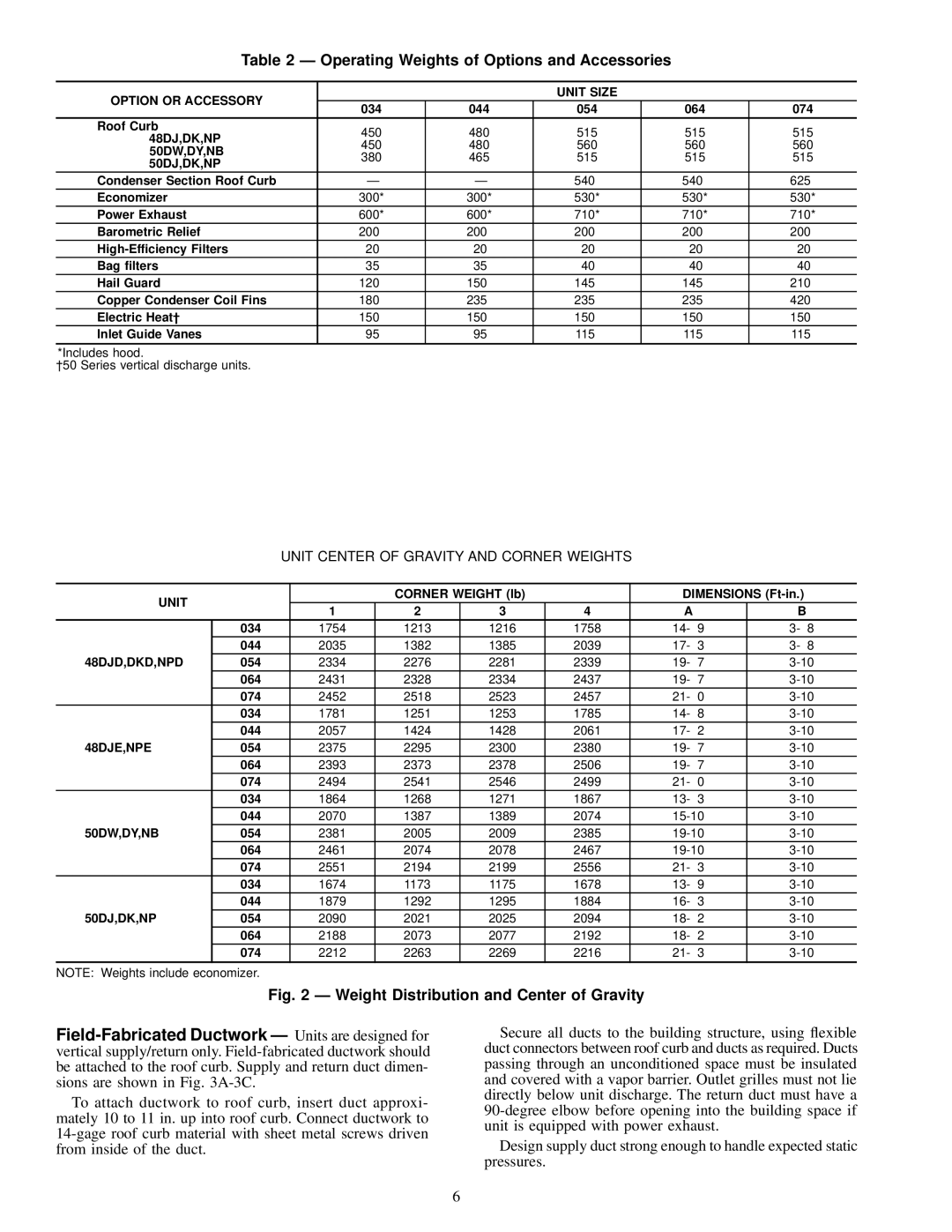
NP034-074 specifications
The Carrier NP034-074 is an advanced rooftop unit designed for commercial heating, ventilation, and air conditioning (HVAC) applications. This unit is part of Carrier’s extensive range of rooftop units that are known for their energy efficiency, reliability, and innovative features. The NP034-074 series is particularly recognized for its robust performance in diverse environmental conditions, making it ideal for a variety of commercial building types.One of the standout features of the NP034-074 is its high-efficiency compressor. Equipped with a scroll compressor, the unit offers enhanced performance and quieter operation compared to traditional reciprocating compressors. This design not only improves energy efficiency but also reduces operating costs over time. The unit is designed to meet or exceed the latest efficiency standards, ensuring that businesses can enjoy optimal indoor comfort while keeping energy consumption low.
The NP034-074 also integrates advanced control technologies that provide users with greater flexibility and ease of operation. The intuitive control system allows for precise temperature management and can be easily integrated with building automation systems. This enables users to monitor and adjust settings remotely, ensuring consistent and efficient climate control throughout the facility.
Another key characteristic of the NP034-074 is its robust construction. Built to withstand various weather conditions, the unit features a galvanized steel cabinet with a powder-coated finish for corrosion resistance. Its design also facilitates easy access for maintenance and service, which minimizes downtime and operational interruptions.
In terms of air distribution, the NP034-074 incorporates a powerful blower system that ensures even and effective airflow throughout the space. This design improves indoor air quality by enhancing ventilation while maintaining comfort levels. Additionally, the unit can be customized with options such as economizers and variable speed fans to optimize performance based on specific building needs.
The NP034-074 is a versatile and reliable choice for businesses looking to enhance their HVAC systems. With its combination of energy efficiency, advanced technology, and robust construction, this rooftop unit stands out as a top choice for commercial climate control solutions.

