CP81 | L1 L2 |
control card | |
| TEST |
| STATUS |
| SET |
CP81 | 74 |
control card | L1 L2 |
| TEST |
| STATUS |
| SET |
EXIT GATE LIMITS ROUTINE (A5 ONLY)
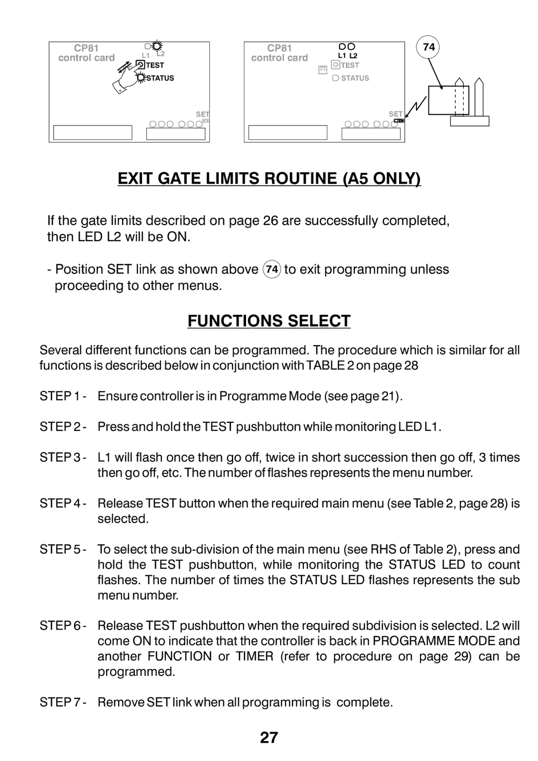
If the gate limits described on page 26 are successfully completed, then LED L2 will be ON.
-Position SET link as shown above 74 to exit programming unless proceeding to other menus.
FUNCTIONS SELECT
Several different functions can be programmed. The procedure which is similar for all functions is described below in conjunction with TABLE 2 on page 28
STEP 1 - Ensure controller is in Programme Mode (see page 21).
STEP 2 - Press and hold the TEST pushbutton while monitoring LED L1.
STEP 3 - L1 will flash once then go off, twice in short succession then go off, 3 times then go off, etc. The number of flashes represents the menu number.
STEP 4 - Release TEST button when the required main menu (see Table 2, page 28) is selected.
STEP 5 - To select the
STEP 6 - Release TEST pushbutton when the required subdivision is selected. L2 will come ON to indicate that the controller is back in PROGRAMME MODE and another FUNCTION or TIMER (refer to procedure on page 29) can be programmed.
STEP 7 - Remove SET link when all programming is complete.
27
