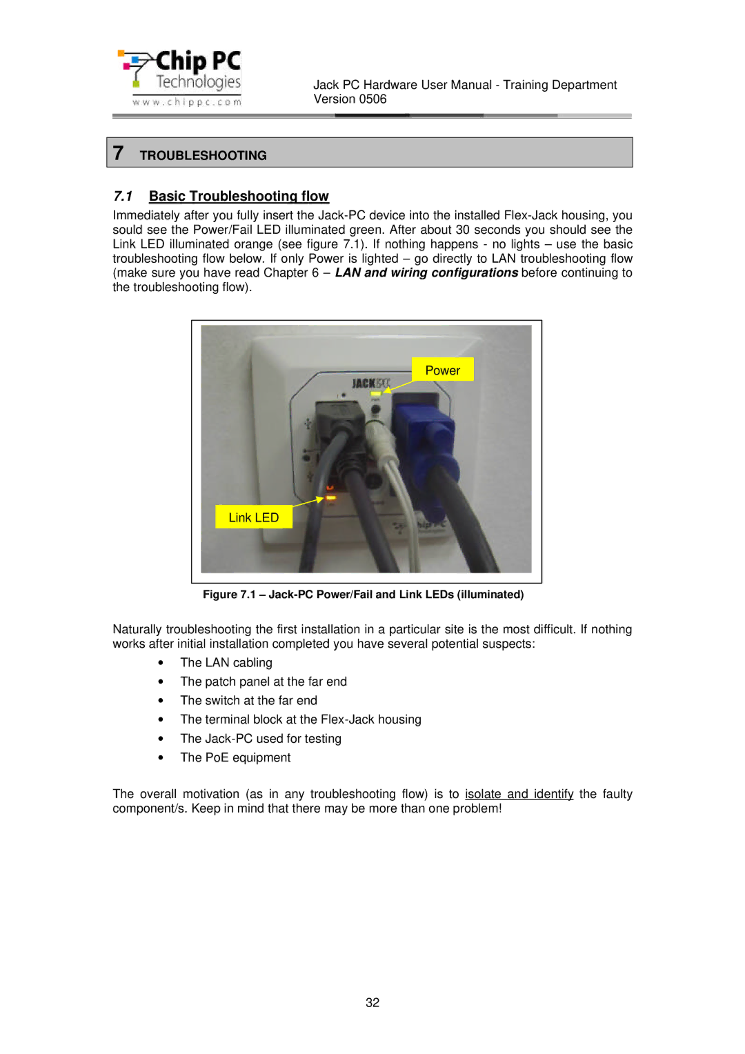
CDC01927 specifications
The Chip PC CDC01927 is a versatile thin client device designed for efficient computing in enterprise environments. This model is known for its energy efficiency, compact design, and powerful performance, making it an ideal choice for businesses looking to optimize their IT infrastructure.One of the key features of the CDC01927 is its robust processing capabilities. It is powered by an Intel CPU, which ensures smooth performance even when running resource-intensive applications. The device supports multiple operating systems, including Windows and Linux-based environments, providing flexibility based on the user’s requirements.
In terms of connectivity, the Chip PC CDC01927 comes equipped with an array of ports including USB 3.0, HDMI, and Ethernet. This enables users to connect multiple peripherals seamlessly, facilitating a productive workspace. The inclusion of Wi-Fi and Bluetooth support also allows for wireless connectivity options, making it easier to integrate with existing networks and devices.
Security is a critical consideration for any endpoint device in a corporate setting, and the CDC01927 does not compromise in this area. It features advanced encryption technologies and secure boot options that help protect sensitive data from unauthorized access. The thin client supports a wide range of security protocols, ensuring compliance with industry standards.
Another standout aspect of the CDC01927 is its ability to deliver centralized management capabilities. Administrators can easily deploy, monitor, and maintain multiple units from a single location. This significantly reduces IT overhead and improves operational efficiency, as updates and configurations can be done remotely.
The CDC01927 is also designed with energy efficiency in mind, consuming less power compared to traditional desktop computers. This not only lowers operational costs but also contributes to a reduced carbon footprint, aligning with sustainability goals.
In conclusion, the Chip PC CDC01927 is an excellent choice for businesses seeking a reliable, secure, and energy-efficient thin client solution. With its powerful processing capabilities, extensive connectivity options, and centralized management features, it stands out as a significant player in the thin client market. Whether for virtual desktop infrastructure (VDI) or cloud computing environments, the CDC01927 meets the diverse needs of modern enterprise environments.

