SERIAL INTERFACE
I |
|
|
|
| A/A' | A'/A |
| ||||||||
N |
|
|
|
|
| ||||||||||
11 |
| M | |||||||||||||
S |
|
|
|
|
|
|
|
|
|
|
|
| |||
|
|
|
|
|
|
|
|
|
|
|
|
| A | ||
T |
|
|
|
|
|
|
|
|
|
|
|
|
| ||
|
|
|
| B/B' | B'/B | S | |||||||||
R |
|
|
|
| |||||||||||
12 |
|
| |||||||||||||
U |
|
|
|
|
|
|
|
|
|
|
|
| T | ||
|
|
|
|
|
|
|
|
|
|
|
| ||||
|
|
|
|
|
|
|
|
|
|
|
|
| E | ||
M |
|
|
|
| COMMON |
| |||||||||
|
|
|
|
| R | ||||||||||
E |
|
|
|
|
|
| |||||||||
| 13 |
|
|
| |||||||||||
N |
|
|
|
|
|
|
|
|
|
|
|
|
|
| |
|
|
|
|
|
|
|
|
|
|
|
|
|
|
| |
T |
|
|
|
|
|
|
|
|
|
|
|
|
|
| |
|
|
|
|
|
|
|
|
|
|
|
|
|
| ||
|
|
|
|
|
|
|
|
|
|
|
|
|
| ||
|
|
|
|
|
|
|
|
|
|
|
|
|
|
|
|
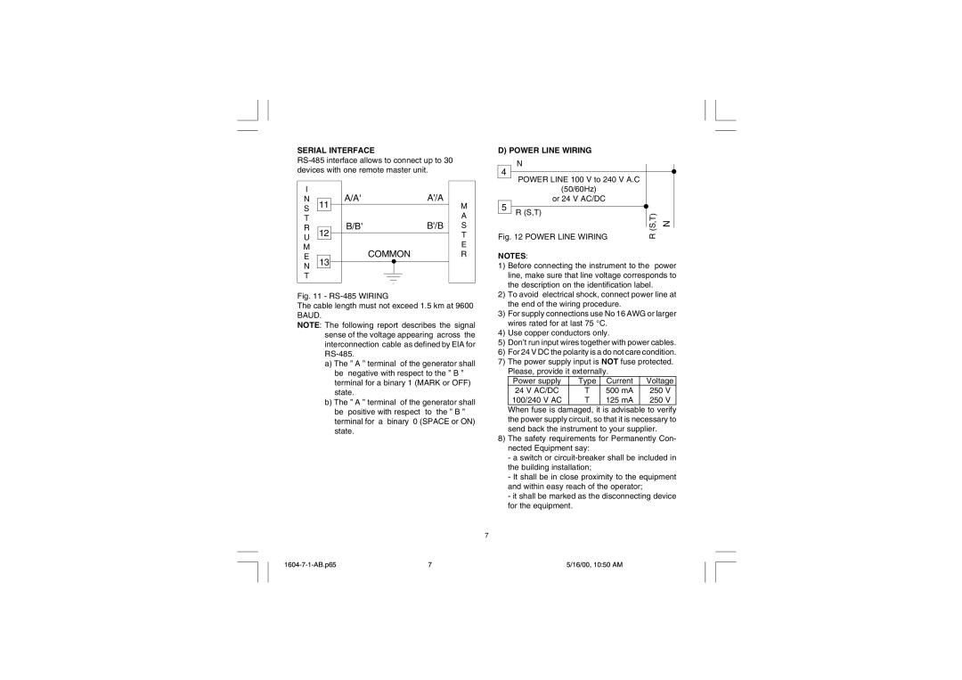
Fig. 11 - RS-485 WIRING
The cable length must not exceed 1.5 km at 9600 BAUD.
NOTE: The following report describes the signal sense of the voltage appearing across the interconnection cable as defined by EIA for
a)The ” A ” terminal of the generator shall be negative with respect to the ” B ” terminal for a binary 1 (MARK or OFF) state.
b)The ” A ” terminal of the generator shall be positive with respect to the ” B ” terminal for a binary 0 (SPACE or ON) state.
D) POWER LINE WIRING
|
|
| N |
|
|
|
|
|
|
| 4 |
|
|
|
|
|
|
| |
|
|
|
|
|
|
|
|
| |
|
| POWER LINE 100 V to 240 V A.C |
|
| |||||
|
|
|
|
| |||||
|
|
| (50/60Hz) |
|
|
|
| ||
|
|
| or 24 V AC/DC |
|
|
|
| ||
| 5 |
| R (S,T) |
|
|
|
| (S,T) | N |
|
|
|
|
|
|
| |||
|
|
|
|
|
|
|
| ||
|
|
|
|
|
|
|
|
| |
| Fig. 12 POWER LINE WIRING | R |
| ||||||
|
|
| |||||||
| NOTES: |
|
|
|
|
|
| ||
| 1) | Before connecting the instrument to the power | |||||||
|
| line, make sure that line voltage corresponds to | |||||||
|
| the description on the identification label. |
| ||||||
| 2) | To avoid electrical shock, connect power line at | |||||||
|
| the end of the wiring procedure. |
|
| |||||
| 3) | For supply connections use No 16 AWG or larger | |||||||
|
| wires rated for at last 75 °C. |
|
| |||||
| 4) | Use copper conductors only. |
|
| |||||
| 5) | Don’t run input wires together with power cables. | |||||||
| 6) | For 24 V DC the polarity is a do not care condition. | |||||||
| 7) | The power supply input is NOT fuse protected. | |||||||
|
| Please, provide it externally. |
|
| |||||
|
|
| Power supply | Type |
| Current |
| Voltage | |
|
|
| 24 V AC/DC | T |
| 500 mA |
| 250 V | |
|
|
| 100/240 V AC | T |
| 125 mA |
| 250 V | |
|
| When fuse is damaged, it is advisable to verify | |||||||
|
| the power supply circuit, so that it is necessary to | |||||||
|
| send back the instrument to your supplier. |
| ||||||
| 8) | The safety requirements for Permanently Con- | |||||||
|
| nected Equipment say: |
|
|
|
| |||
|
| - a switch or | |||||||
the building installation;
- It shall be in close proximity to the equipment and within easy reach of the operator;
- it shall be marked as the disconnecting device for the equipment.
7
7 | 5/16/00, 10:50 AM |