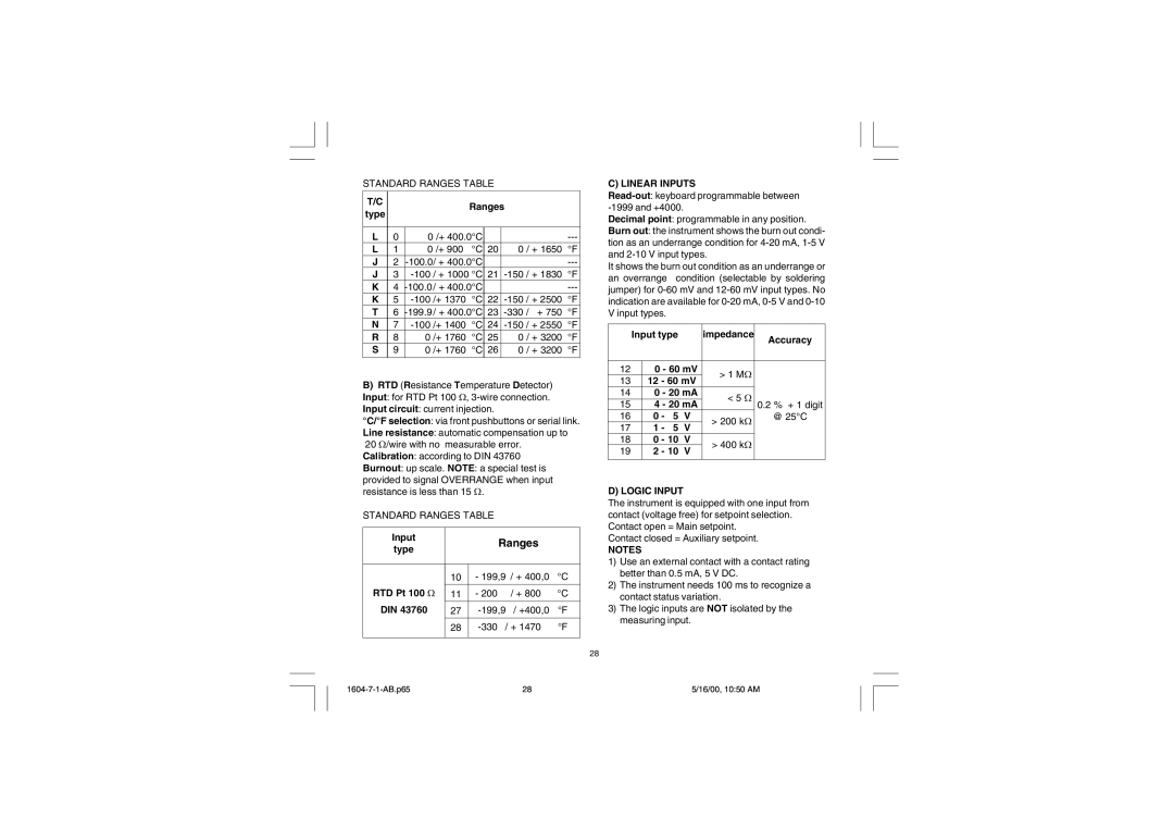
STANDARD RANGES TABLE
T/C |
|
|
| Ranges |
|
| ||
type |
|
|
|
|
| |||
|
|
|
|
|
|
|
| |
|
|
|
|
|
|
| ||
L | 0 | 0 /+ 400.0°C |
|
|
| |||
L | 1 | 0 /+ 900 | °C | 20 | 0 | / + 1650 °F | ||
J | 2 |
|
|
| ||||
J | 3 | / + 1000 °C | 21 | |||||
K | 4 |
|
|
| ||||
K | 5 | /+ 1370 °C | 22 | |||||
T | 6 | 23 | °F | |||||
N | 7 | /+ 1400 | °C | 24 | ||||
R | 8 | 0 | /+ 1760 | °C | 25 | 0 | / + 3200 | °F |
S | 9 | 0 | /+ 1760 | °C | 26 | 0 | / + 3200 | °F |
|
|
|
|
|
|
|
|
|
B)RTD (Resistance Temperature Detector) Input: for RTD Pt 100 W,
°C/°F selection: via front pushbuttons or serial link.
Line resistance: automatic compensation up to 20 W/wire with no measurable error. Calibration: according to DIN 43760 Burnout: up scale. NOTE: a special test is
provided to signal OVERRANGE when input resistance is less than 15 W.
STANDARD RANGES TABLE
Input |
| Ranges |
| |
type |
|
| ||
|
|
|
| |
|
|
|
|
|
| 10 | - 199,9 | / + 400,0 | °C |
RTD Pt 100 W | 11 | - 200 | / + 800 | °C |
DIN 43760 | 27 | / +400,0 | °F | |
| 28 | °F | ||
|
|
|
|
|
C) LINEAR INPUTS
Decimal point: programmable in any position.
Burn out: the instrument shows the burn out condi- tion as an underrange condition for
It shows the burn out condition as an underrange or an overrange condition (selectable by soldering jumper) for
| Input type |
| impedance | Accuracy | ||||
|
|
|
|
|
|
|
| |
|
|
|
|
|
| |||
12 |
| 0 - 60 mV | > 1 MW |
| ||||
13 |
| 12 | - 60 mV |
| ||||
|
|
|
| |||||
14 |
| 0 - 20 mA | < 5 | W |
| |||
15 |
| 4 - 20 mA | 0.2 % + 1 digit | |||||
|
|
| ||||||
16 |
| 0 | - | 5 V | > 200 kW | @ 25°C | ||
17 |
| 1 | - | 5 | V |
| ||
|
|
|
| |||||
18 |
| 0 | - 10 | V | > 400 kW |
| ||
19 |
| 2 | - 10 | V |
| |||
|
|
|
| |||||
|
|
|
|
|
|
|
|
|
D) LOGIC INPUT
The instrument is equipped with one input from contact (voltage free) for setpoint selection. Contact open = Main setpoint.
Contact closed = Auxiliary setpoint.
NOTES
1)Use an external contact with a contact rating better than 0.5 mA, 5 V DC.
2)The instrument needs 100 ms to recognize a contact status variation.
3)The logic inputs are NOT isolated by the measuring input.
28
28 | 5/16/00, 10:50 AM |
