INDUCTIVE LOADS
High voltage transients may occur switching inductive loads.
Through the internal contacts these transients may introduce disturbances which can affect the performance of the instrument.
For the OUT 2 and OUT 3, the internal protection (varistor) assures a correct protection up to 0.5 A of inductive component.
The same problem may occur when a switch is used in series with the internal contacts as shown in Fig. 9.
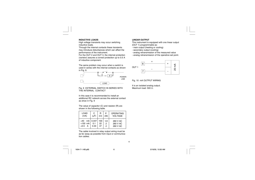
LINEAR OUTPUT
This instrument is equipped with one linear output (OUT 1) programmable as:
-main output (heating or cooling)
-secondary output (cooling)
-analog retransmission of the measured value
-analog retransmission of the operative set point.
|
|
| + |
| + |
|
| |
| 6 |
|
| mA | ||||
|
|
|
|
| ||||
|
|
| ||||||
OUT 1 | _ |
|
|
| ||||
|
|
| 20 | |||||
|
|
|
| _ |
| |||
|
|
|
|
|
|
| ||
|
| 7 |
|
|
|
| ||
|
|
|
|
|
|
| ||
|
|
|
|
|
|
| ||
C
R
LOAD
POWER
LINE
Fig. 10 mA OUTPUT WIRING
Fig. 9 EXTERNAL SWITCH IN SERIES WITH THE INTERNAL CONTACT
In this case it is recommended to install an additional RC network across the external contact as show in Fig. 9
The value of capacitor (C) and resistor (R) are shown in the following table.
LOAD | C | R | P. | OPERATING | |
(mA) | (mF) | (W) | (W) | VOLTAGE | |
|
|
|
|
|
|
<40 | mA | 0.047 | 100 | 1/2 | 260 V AC |
<150 mA | 0.1 | 22 | 2 | 260 V AC | |
<0.5 | A | 0.33 | 47 | 2 | 260 V AC |
|
|
|
|
|
|
The cable involved in relay output wiring must be as far away as possible from input or communica- tion cables.
6
It is an isolated analog output. Maximum load: 500 W.
6 | 5/16/00, 10:50 AM |