B)LOGIC INPUT Safety note:
1) Do not run logic input wiring together with power cables.
2) Use an external dry contact capable of switching 0.5 mA, 5 V DC.
3) The instrument needs 100 ms to recognize a contact status variation.
4) The logic inputs are NOT isolated by the measuring input
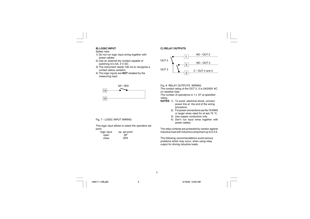
C) RELAY OUTPUTS
1
OUT 2
3
OUT 3
2
NO - OUT 2
NO - OUT 3
C - OUT 2 and 3
SP / SP2
14
15
Fig. 7 - LOGIC INPUT WIRING
This logic input allows to select the operative set point.
logic input
open close
Fig. 8 RELAY OUTPUTS WIRING
The contact rating of the OUT 2, 3 is 2A/250V AC on resistive load.
The number of operations is 1 x 10⁵ at specified rating.
NOTES 1) To avoid electrical shock, connect power line at the end of the wiring procedure.
2)For power connections use No 16 AWG or larger wires rated for at last 75 °C.
3)Use copper conductors only.
4)Don’t run input wires together with power cables.
The relay contacts are protected by varistor against inductive load with inductive component up to 0.5 A.
The following recommendations avoid serious problems which may occur, when using relay output for driving inductive loads.
5
5 | 5/16/00, 10:50 AM |