Americas Headquarters
Text Part Number OL-14521-01
Cisco Systems, Inc. All rights reserved
Iii
Parts List
Overview A-1
Carton 13 of 58 Brackets, 69-1632-xx, CTS3K-STRUCTURE A-6
CTS32-STRUCTURE, 69-1854-01 A-17
Vii
Viii
Conventions
Preface
Introduction
Related Documentation
Overview
Chapter Organization
Building the Second Row Table Assembly
Conventions and Terminology
Tools and Equipment List
Uncrating and Unpacking
Claw hammer or small pry bar
Overview Tools and Equipment List
Key Part Description Part Number Qty Ctn
Building the Display Assembly
Parts List
Leveling feet
Attach the Codec Safety trays to the Front Foot stabilizers
Codec Safety trays
Rear and Front Foot stabilizers
Left and Right Display Shelf supports
Attach the Display Tilt brackets to each Display structure
Display Tilt brackets
Camera Assembly bracket
Upper and Lower Support crossbars
201108
Positioning the Display Structures
Mounting and Leveling the Plasma Displays
Inch high-definition display
Left, center, and right Plasma displays
201111
Purpose of Leveling the Plasma displays
Leveling Alignment Points
Leveling Goals
Level the Display shelves along the X and Y axes
Cisco TelePresence System
Level the Plasma displays along the X and Y axes
Align the edges of Plasma displays
Cisco TelePresence System OL-14521-01
Apply the Black Buffer strips
Building the Display Shelf Assembly
Accessory Cabinet
Building the Display Shelf Assembly Parts List
Attach the Display shelf hardware
Display shelf hardware
Attach the left Display shelf
Left Display shelf
Attach the center Display shelf
Center Display shelf
Attach the right Display shelf
Right Display shelf
Accessory Cabinet
OL-14521-01
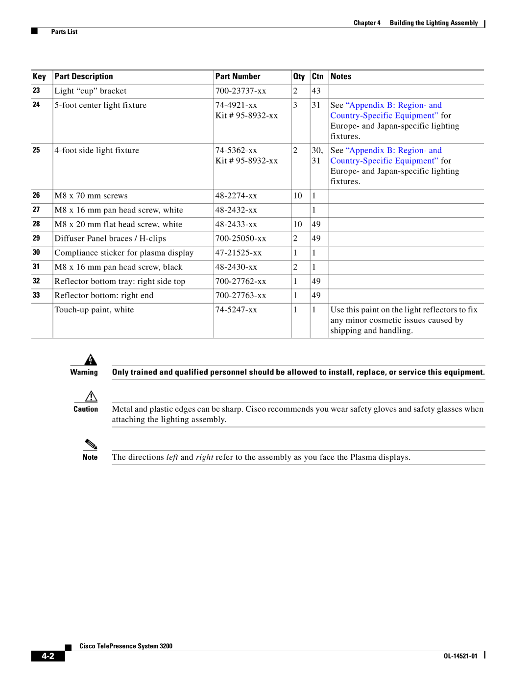
Building the Lighting Assembly
Foot side light fixture 74-5362-xx
Europe- and Japan-specific lighting
Fixtures
Support struts and Lighting Support brackets
Left and Right outer Support brackets from Figure
Four inner Support brackets from Figure
Four End structure brackets
Three Reflector bottom trays
Two Reflector bottom spacers
Left and Right vertical Reflector Bottom ends
Light Cup bracket
Three 5-foot Light fixtures
10 Left and Right 4-foot Side Light fixtures
Attach the two center Metal Trim panels
11 Two center Metal Trim panels
Attach the two side Metal Trim panels
12 Two side Metal Trim panels
Attach the center Plastic Diffuser panel
13 Center Plastic Diffuser panel
14 Left and Right Plastic Diffuser panels
Four L-brackets
16 Two vertical Plastic Diffuser panels
17 Plastic Diffuser Panel brace
18 Center Reflector top
19 Left and Right Reflector tops
2017
21 Left and Right vertical Reflector ends
22 Left and Right corner Reflector Transition pieces
23 Two Metal Trim panels
Building the Lighting Assembly Parts List
Building the First Row Table Assembly
Panel Assembly
Number
Metal packaging braces and their Molded foam bumpers
12. The other three legs each have two attachment brackets
22 23
Assemble the I/O modules for the inner molded foam bumpers
Right Wing Tabletop Section
Right Table segment
Attach the right most Table Leg
Right Most Table Leg
Center Table segment
Attach the right center Table leg
Right center Table leg
10 Left Table segment
Attach the left center Table leg
11 Left center Table leg
Attach the left most Table leg
12 left Most Table Leg
13 Microphone Assembly
14 Left connecting Tabletop section
Attach the center Privacy panel
Rotated for clarity
16 Privacy Panel Assembly
Attach the left Privacy panel
17 Privacy Panel Assembly
Attach the right Privacy panel
18 Privacy Panel Assembly
Attach the right wing Privacy panel
Building the Second Row Table Assembly
Building the Second Row Table Assembly Parts List
To Appendix B Region-
Metal packaging braces and their Molded foam bumpers
204149
435
204102
Gutter Panel
Attach the gutter panel to the table legs
204105
204106
Attach the left gutter panels to the remaining table legs
Left Gutter Panels
Attach the right gutter panels to the remaining table legs
10 Right Gutter Panels
47 48
12 Foam Bumper Assembly
Insert the second row PDUs in the lower cable gutters
5554
14 Floating Brackets, Type
13 56
Attach the privacy panel hangers to the table assembly
1135
17 Tabletop Sections 1 and 2, Spline And Draw Bolts
18 Tabletop Section
Join table to table using the draw bolts and spline
19 Tabletop Section
20 Tabletop Left
21 Tabletop Right
22 Left Tabletop End, Draw Bolts, Spline and Alignment Plate
Attach the Right tabletop end
23 Right Tabletop End
Attach tabletop sections 1 and 2 to the table leg
24 Tabletop Sections 1 and 2 and Table Leg
Attach tabletop sections 1 and 3 to the table leg
25 Tabletop Sections 1 and 3 and Table Leg
Attach tabletop sections 2 and 4 to the table leg
26 Tabletop Sections 2 and 4 and Table Leg
Attach tabletop sections 3 and 5 to the table leg
27 Tabletop Sections 3 and 5 and Table Leg
Attach tabletop sections 4 and 5 to the table leg
28 Tabletop Sections 4 and 5 and Table Leg
Attach the reinforcement screws for the gutter panels
29 Gutter Panel Reinforcement Screws
204123
32 Privacy Panel Alignment Bracket
33 Privacy Panel Alignment Bracket
35 Privacy Panel Alignment Bracket
37 Right Privacy Panel Alignment Bracket
38 Microphone Assembly
39 Privacy Panel
Attach the privacy panel for to the table assembly
40 Privacy Panel
41 Privacy Panel
42 Privacy Panel
Attach the privacy panel for left to the table assembly
43 Left Privacy Panel
Attach the privacy panel for right to the table assembly
44 Privacy Panel
45 Adjusting the Privacy Panels
Cable Cover
47 Privacy Panel End Pieces
48 Second Row Table Positioning
Assembling the Remaining Cisco TelePresence Elements
Camera Assembly
Projector Assembly
Assembly
Projector Screen Assembly, Type
Target Assembly
Cisco Unified IP Phone CP-7975G
Switch Bracket
Horizontal bar 700-23960-xx M4 x 20 mm screws 48-0654-xx
Camera Assembly
Projector Assembly
Attach the projector to the projector mounting bracket
201169
201170
Codec Assembly
Attach the Cable management bars to the three Codecs
Attach the Codec attachment brackets to the three Codecs
201177
Speaker Assembly
201180
10 Speaker Assembly
Attach the Speakers to the Speaker boards
11 Projector Screen Assembly
Attach the Projector screen to the Display shelves
Attach the audio/video extension unit to its bracket
12 Audio/Video Expansion Unit and Bracket
13 Audio/Video Extension Unit
14 Auxiliary Control Unit
15 Camera Target Assembly
Routing Power and Signal Cables
Specific part numbers
Routing Power and Signal Cables Parts List
Dual PDU installation to left accessory cabinet
Right side PDU installation to right accessory cabinet
Table assembly PDU attachment to the center Privacy panel
Route the power cables for the first row table assembly
First Row Table Assembly Cable Routing
Table assembly Signal Cable Routing
Route the second row microphone cables
Microphone Cable Routing
Ethernet Cable Routing
Route the power cables for the second row table
Second Row Table Power Cable Routing
IP Phone Signal VGA Peripheral Projector HD Video to Codec
10 Cabling the Microphones
Attach and route the cables for the speakers
11 Cabling the Speakers
Auxiliary Control Unit
13 Cabling the Plasma Display
14 Cabling the Camera Assembly
Attach the cables between the codecs
15 Inter-Codec Cabling
Connect the power cables for the codecs
16 Cabling the Codecs
Auxiliary Control Unit Projector
Document Camera Optional
Routing Power and Signal Cables Parts List
OL-14521-01
First-Time Setup
Loading CTS Administration Software
Hood Assembly Figure
10-1
Bootup Completed
10-2
10-3
System IP Address
Configuring an Alternate Tftp Server Optional
Setting Up CTS Components
To set up the CTS components
10-4
10-5
Setting Up the Displays
Selecting the Light Level
Setting Up the Cameras
Troubleshooting Displays
Problem Possible Cause Action
Only
Start the Software Setup
Auto Adjust
Attach the Camera Targets
Align the Camera
10-8
Camera Mounting Plate
10-9
Correct Camera Target Alignment-Center Display
Attaching the Camera Hood Assembly
Show All Camera Targets
Flipping the Video Image
Focus the Camera
10-11
Troubleshooting Cameras
Use -2to troubleshoot problems with cameras
10-12
Setting Up the Speakers
Setting Up the Microphones
Troubleshooting Speakers
Problem Possible Cause Possible Solution
Setting Up the Projector
Troubleshooting Microphones
Use -4to troubleshoot problems with microphones
To set up the projector, complete the following steps
10-15
Use -5to troubleshoot problems with presentation devices
10-16
10-17
Other Devices
10-18
Cleaning the Plasma displays
Use & Care Guide
Maintaining the Tabletop
11-1
Cleaning the Camera lens Maintaining the Projector
11-2
12-1
Powering On the System
Field-Replaceable Unit Guide
12-2
Replacing the Camera Cluster-Part Number
Required Information, Tools, and Equipment
Removing and Replacing the Camera Cluster
12-3
Re-attach the camera hood and lens hood
12-4
Removing Audio Components
12-5
Removing the Camera Cluster
Removing the Left Door
Removing a Display Shelf
12-6
Removing the Display Screen and Completing the Procedure
12-7
Perform the display adjustment procedure
Replacing a Speaker-Part Number CTS-LDSPKR
Removing and Replacing a Speaker
12-8
12-9
Removing and Replacing a Codec
12-10
12-11
12-12
Replacing a Microphone-Part Number CTS-MIC
Removing and Replacing a First Row Microphone
Removing and Replacing a Second Row Microphone
12-13
12-14
Replacement Bulbs
Replacing a Light Fixture-Part Number CTS-LIGHT-FIXT
12-15
Replacing a Light Fixture
Plug the light fixture into the Auxiliary Control Unit
Replacing the Auxiliary Control Unit-Part Number
12-16
12-17
Replacement process
Replacing the Projector Lamp-Part Number
Replacing the Projector-Part Number CTS-PRJTR-GEN1
12-18
Replacing a PDU-Part Number CTS-PWR-PDU
12-19
12-20
Replacing a Display Shelf
Removing and Replacing a Display Shelf Row Table Section
12-21
12-22
Replacing a First Row Table Top Section
Removing and Replacing a First Row Table Top Section
12-23
12-24
Replacing a Second Row Table Top Section
Removing and Replacing a Second Row Table Top Section
12-25
12-26
Attach the gutter panel for the table top section
Attach the privacy panel alignment bracket
Appendix a Parts List Sorted by Carton
Carton 1 of 58 Mechanical Accessory Kit, CTS3K-ACC-KIT
Sub-Kit ID Chapter Parts List
Overview
OL-14521-01
Specific part
Numbers
Sub-Kit ID
Kit ID Number Part Number Part Description Qty Reference
Carton 4 of 58 Camera Cluster
Carton 7 of 58 Projector, 74-4824-xx, CTS-PRJTR-GEN1
Xxxx-xx Power cord Chapter
Carton 8 of 58 Speaker, 74-4740-xx, CTS-LDSPKR
Carton 9 of 58 Speaker, 74-4740-xx, CTS-LDSPKR
Carton 10 of 58 Speaker, 74-4740-xx, CTS-LDSPKR
Carton 15 of 58 Front Foot Stabilizer
Carton 12 of 58 Camera Assembly Bracket
Carton 14 of 58 Privacy Panel, Right Wing
Carton 16 of 58 Front Foot Stabilizer
Carton 17 of 58 Front Foot Stabilizer
74-4881-xx 74-4605-xx Inch high-definition display Chapter
Carton 22 of 58 Auxiliary Control Unit, CTS-LIGHT-CTRL
Subkit ID
74-4605-xx Inch high-definition display Chapter
74-5361-xx 74-5361-01 Foot light fixture Chapter
Lighting fixtures for
Europe and Japan
Country-specific
74-5362-xx 74-5362-01 Foot light fixture Chapter
74-5362-xx 74-4921-01 Foot light fixture Chapter
Carton 36 of 58 Display Structure
Carton 33 of 58 Support Crossbars
Carton 35 of 58 Display Structure
Carton 37 of 58 Display Structure
Carton 40 of 58 Secondary Codec
CTS-CODEC-SEC
Carton 44 of 58 Lighting Assembly
Carton 45 of 58 Projector Bracket
Carton 49 of 58 Lighting Assembly
69-1854-01
Subkit ID Chapter Parts
Number Part Number Part Description Qty
Carton 52 of 58 Tabletop Leg Base
Carton 53 of 58 Tabletop Leg Base
Carton 56 of 58 Projector Bracket
Carton 55 of 58 Lighting Assembly
Carton 54 of 58 Tabletop Leg Base
OL-14521-01
Appendix B Region- and Country-Specific Equipment
Asia Pacific
Argentina
Part Description Part Number Qty
Europe
Australia
China
India, UAE, South Africa
Israel
Italy
Japan
United Kingdom
North America
Switzerland