Configuring Virtual Port Channels

Configuring a vPC Keepalive Link and Messages

Procedure


Command or Action

Purpose

Step 1

switch# configure terminal

Enters configuration mode.

Step 2

switch(config)# vpc domain domain-id

Creates a vPC domain on the switch if it does


not already exist, and enters the vpc-domain


configuration mode.

Step 3 switch(config-vpc-domain)# peer-keepalive destination ipaddress [hold-timeoutsecs interval msecs {timeout secs} precedence {prec-value network internet critical flash-override flash immediate priority routine} tos {tos-value max-reliability max-throughput min-delay min-monetary-cost normal} tos-byte

tos-byte-value} source ipaddress vrf {name

management vpc-keepalive}]

Step 4 switch(config-vpc-domain)# vpc

peer-keepalive destination ipaddress source

ipaddress

Configures the IPv4 address for the remote end of the vPC peer-keepalive link.

Note The system does not form the vPC peer

link until you configure a vPC peer-keepalive link.

The management ports and VRF are the defaults

(Optional)

Configures a separate VRF instance and puts a Layer 3 port from each vPC peer device into that VRF for the vPC peer-keepalive link.

Step 5

switch# show vpc peer-keepalive

(Optional)


Displays information about the configuration for


the keepalive messages.

Step 6

switch# copy running-config startup-config

(Optional)


Copies the running configuration to the startup


configuration.

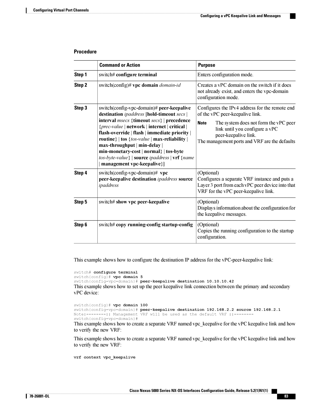
This example shows how to configure the destination IP address for the vPC-peer-keepalive link:

switch# configure terminal switch(config)# vpc domain 5

switch(config-vpc-domain)#peer-keepalive destination 10.10.10.42

This example shows how to set up the peer keepalive link connection between the primary and secondary vPC device:

switch(config)# vpc domain

100

switch(config-vpc-domain)#

peer-keepalive destination 192.168.2.2 source 192.168.2.1

Note:--------

:: Management

VRF will be used as the default VRF ::--------

switch(config-vpc-domain)#


This example shows how to create a separate VRF named vpc_keepalive for the vPC keepalive link and how to verify the new VRF:

This example shows how to create a separate VRF named vpc_keepalive for the vPC keepalive link and how to verify the new VRF:

vrf context vpc_keepalive

Cisco Nexus 5000 Series NX-OS Interfaces Configuration Guide, Release 5.2(1)N1(1)

78-26881-OL

83

Page 95
Image 95
Cisco Systems N5KC5596TFA manual Management vpc-keepalive, Peer-keepalive destination ipaddress source

N5KC5596TFA specifications

The Cisco Systems N5KC5596TFA is a high-performance data center switch designed specifically for modern architectures requiring low-latency, high-bandwidth connectivity. As part of the Nexus 5000 series, the N5KC5596TFA addresses the needs of virtualized environments, cloud computing, and highly dynamic workloads, making it an essential choice for enterprises and service providers.

One of the standout features of the N5KC5596TFA is its impressive port density. The switch offers 48 10 Gigabit Ethernet (10GbE) ports and 4 40 Gigabit Ethernet (40GbE) uplinks, providing flexibility to connect a variety of devices and ensuring high throughput across the network. This port configuration is ideal for connecting multiple servers and storage devices, making it perfect for environments with significant data traffic.

The switch supports a range of advanced technologies such as Virtual Extensible LAN (VXLAN) for improving scalability and multi-tenancy in data center networks. VXLAN encapsulates Layer 2 Ethernet frames within Layer 4 UDP packets, allowing for a larger address space and effective overlay networking, which is crucial for cloud deployments.

Another notable aspect of the N5KC5596TFA is its support for Data Center Bridging (DCB), which enhances the reliability and performance of Ethernet networks. DCB features like Priority Flow Control (PFC) and Enhanced Transmission Selection (ETS) help to minimize data loss and ensure Quality of Service (QoS) for various types of traffic, including storage and regular data, which is critical in a converged infrastructure.

Security is also a priority with the N5KC5596TFA, as it comes equipped with features such as Access Control Lists (ACLs) and port security, helping to safeguard the network from unauthorized access and potential threats.

In terms of management, the switch offers integration with Cisco's Data Center Network Manager (DCNM), providing tools for monitoring, management, and automation, which simplifies operational tasks. Additionally, it supports Cisco's Application Centric Infrastructure (ACI), enabling a more comprehensive and application-focused approach to networking.

Overall, the Cisco Systems N5KC5596TFA is engineered for organizations looking to build robust, highly efficient, and secure data center environments. Its combination of high density, versatile connectivity options, and advanced networking technologies makes it a powerful solution for meeting the demands of today’s enterprise workloads.