Chapter 5 Installing Memory in the Router
Replacing DRAM and SDRAM
Table
Bank 0 | Bank 1 | Bank 2 | Bank 3 | Total |
(SIMM 0) | (SIMM 1) | (SIMM 2) | (SIMM 3) | Memory |
|
|
|
|
|
16 MB | 16 MB | 8 | 8 | 48 MB |
|
|
|
|
|
16 MB | 16 MB | 16 MB | 16 MB | 64 MB |
|
|
|
|
|
32 | 32 | Not installed | Not installed | 64 MB |
32 | 32 | 4 MB | 4 MB | 72 MB |
|
|
|
|
|
32 | 32 | 8 MB | 8 MB | 80 MB |
|
|
|
|
|
32 | 32 | 8 | 8 | 80 MB |
|
|
|
|
|
32 | 32 | 16 MB | 16 MB | 96 MB |
|
|
|
|
|
32 | 32 | 32 | 32 | 128 MB |
|
|
|
|
|
1.8 MB =
2.8
3.32
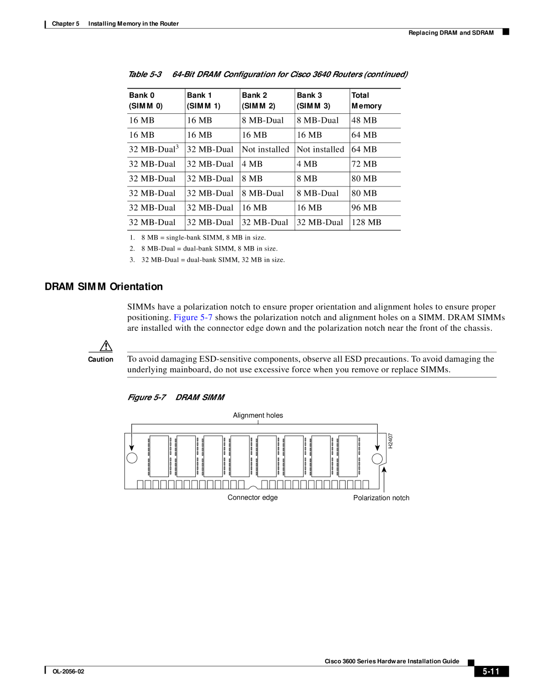
DRAM SIMM Orientation
SIMMs have a polarization notch to ensure proper orientation and alignment holes to ensure proper positioning. Figure
Caution To avoid damaging
Figure 5-7 DRAM SIMM
Alignment holes
H2407
Connector edge | Polarization notch |
Cisco 3600 Series Hardware Installation Guide
|
| ||
|
|