Performing a Basic Configuration
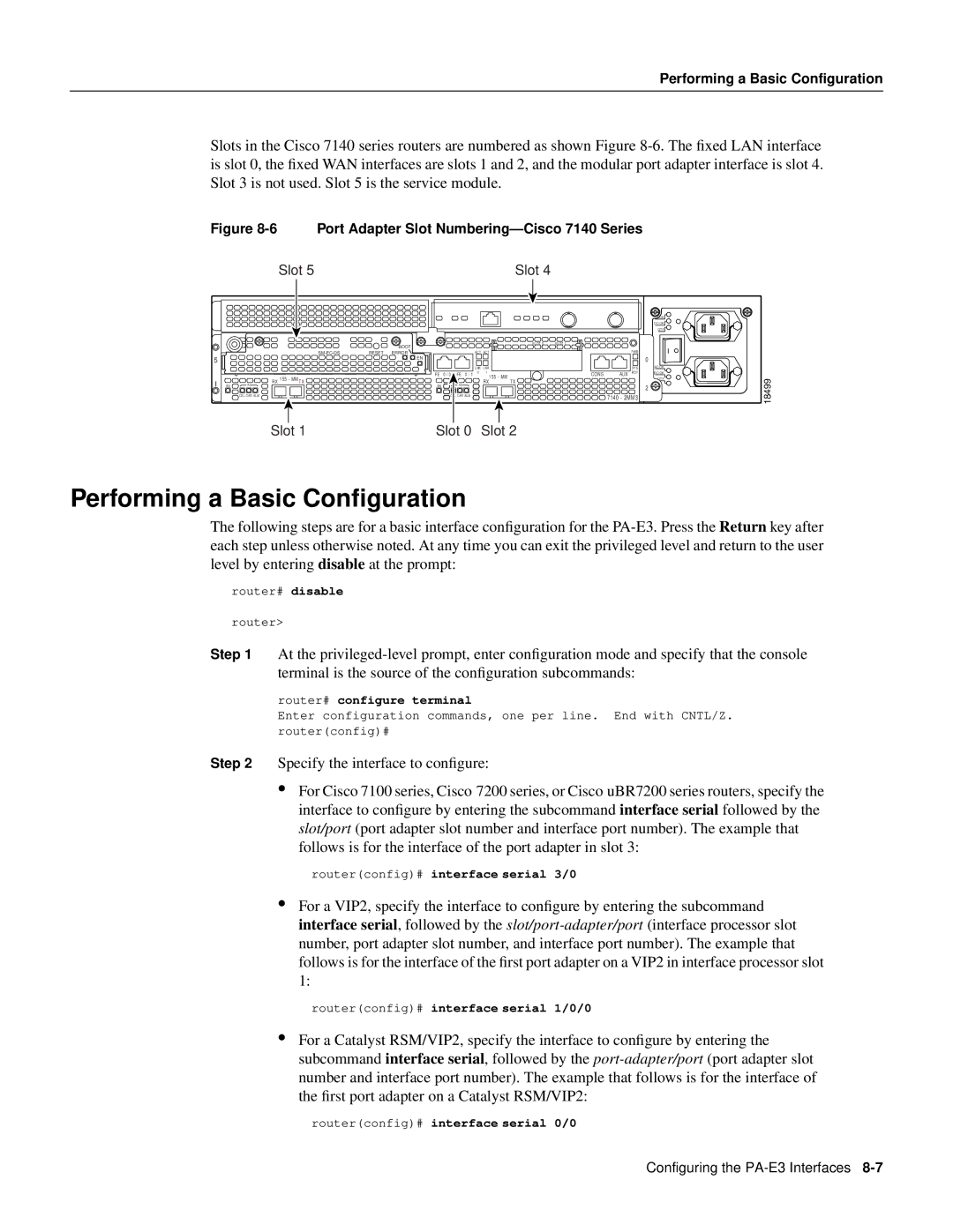
Slots in the Cisco 7140 series routers are numbered as shown Figure
Figure 8-6 Port Adapter Slot Numbering—Cisco 7140 Series
Slot 5 | Slot 4 |
BOOT |
RESET ERROR |
5![]()
![]()
![]()
![]()
![]()
![]() EN
EN
IRX 155 - MM TX
ENRX
CEL CAR ALM
SLOT 0 | SLOT 1 |
|
|
|
|
|
|
|
|
| ACT | ACT |
|
|
|
|
|
|
|
|
|
| LNK | LNK |
|
|
|
|
|
|
|
|
|
|
| ||
|
|
|
|
|
|
|
|
| 0 | 1 |
|
FE 0 / 0 FE 0 / 1 |
| 155 - MM | |||||||||
|
|
|
|
|
|
|
|
|
| ||
RX TX
EN | RX |
CEL CAR ALM
|
|
|
|
|
|
|
|
| PWR |
|
|
|
|
|
|
|
|
| SYS |
|
|
|
|
|
|
|
|
| |
CONS |
|
|
| AUX | RDY | ||||
7140 - 2MM3
| AC OK |
|
| DC OK |
|
| OTF |
|
0 |
|
|
| AC OK |
|
| DC OK |
|
| OTF | 18499 |
2 |
| |
|
|
Slot 1 | Slot 0 Slot 2 |
Performing a Basic Configuration
The following steps are for a basic interface configuration for the
router# disable
router>
Step 1 At the
router# configure terminal
Enter configuration commands, one per line. End with CNTL/Z. router(config)#
Step 2 Specify the interface to configure:
•For Cisco 7100 series, Cisco 7200 series, or Cisco uBR7200 series routers, specify the interface to configure by entering the subcommand interface serial followed by the slot/port (port adapter slot number and interface port number). The example that follows is for the interface of the port adapter in slot 3:
router(config)# interface serial 3/0
•For a VIP2, specify the interface to configure by entering the subcommand interface serial, followed by the
router(config)# interface serial 1/0/0
•For a Catalyst RSM/VIP2, specify the interface to configure by entering the subcommand interface serial, followed by the
router(config)# interface serial 0/0
Configuring the