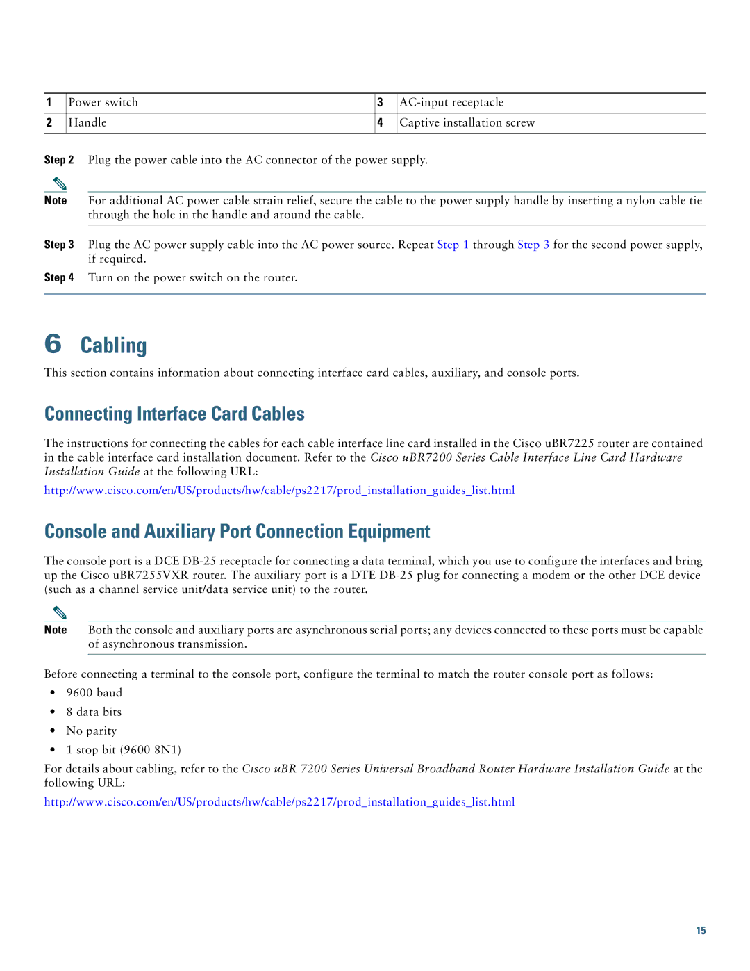
1 | Power switch | 3 | |
|
|
|
|
2 | Handle | 4 | Captive installation screw |
|
|
|
|
Step 2 Plug the power cable into the AC connector of the power supply.
Note For additional AC power cable strain relief, secure the cable to the power supply handle by inserting a nylon cable tie through the hole in the handle and around the cable.
Step 3 Plug the AC power supply cable into the AC power source. Repeat Step 1 through Step 3 for the second power supply, if required.
Step 4 Turn on the power switch on the router.
6Cabling
This section contains information about connecting interface card cables, auxiliary, and console ports.
Connecting Interface Card Cables
The instructions for connecting the cables for each cable interface line card installed in the Cisco uBR7225 router are contained in the cable interface card installation document. Refer to the Cisco uBR7200 Series Cable Interface Line Card Hardware Installation Guide at the following URL:
http://www.cisco.com/en/US/products/hw/cable/ps2217/prod_installation_guides_list.html
Console and Auxiliary Port Connection Equipment
The console port is a DCE
Note Both the console and auxiliary ports are asynchronous serial ports; any devices connected to these ports must be capable of asynchronous transmission.
Before connecting a terminal to the console port, configure the terminal to match the router console port as follows:
•9600 baud
•8 data bits
•No parity
•1 stop bit (9600 8N1)
For details about cabling, refer to the Cisco uBR 7200 Series Universal Broadband Router Hardware Installation Guide at the following URL:
http://www.cisco.com/en/US/products/hw/cable/ps2217/prod_installation_guides_list.html
15
