Installation Tools and Equipment
The tools and equipment listed below are recommended as the minimum necessary to install the Cisco uBR7225VXR router. Other equipment may include test equipment to check electronic and optical signal levels, power levels, and communications links.
•
•Number 2 Phillips screwdriver
•
•
•Antistatic mat or antistatic foam and electrostatic discharge (ESD) grounding strap or the disposable ESD strap
•Wire stripper and crimping tool
•The accessory kit comes with ground lugs and M5 screws with captive, locking washers
•
3Installation Guidelines
This section contains information about power and cabling guidelines, workbench or tabletop installation, and
Power Guidelines
Follow these precautions and recommendations when planning power connections to the Cisco uBR7225VXR router:
•Check the power at your site before installation and periodically after installation to ensure that you are receiving clean power. Install a power conditioner if necessary.
•Provide proper grounding. A grounding lug mount is provided on the rear of the chassis.
•Make sure that the frame ground is tied to a single building ground.
•Use a
Cabling Guidelines
When planning the location of a new system, keep in mind signal type, signal speed, and transmission medium, as well as distance limitations for signaling, EMI, and connector compatibility. Use this information as a guideline in planning your network connections before installing the Cisco uBR7225VXR router.
Ethernet and Fast Ethernet Connections
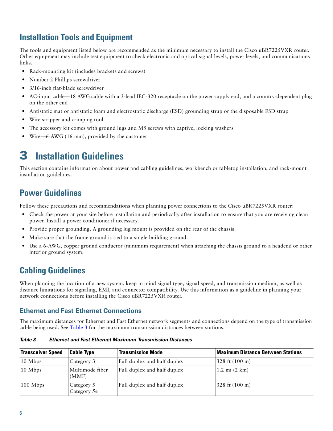
The maximum distances for Ethernet and Fast Ethernet network segments and connections depend on the type of transmission cable being used. See Table 3 for the maximum transmission distances between stations.
Table 3 | Ethernet and Fast Ethernet Maximum Transmission Distances |
| ||
|
|
|
| |
Transceiver Speed | Cable Type | Transmission Mode | Maximum Distance Between Stations | |
|
|
|
|
|
10 Mbps |
| Category 3 | Full duplex and half duplex | 328 ft (100 m) |
|
|
|
|
|
10 Mbps |
| Multimode fiber | Full duplex and half duplex | 1.2 mi (2 km) |
|
| (MMF) |
|
|
|
|
|
|
|
100 Mbps |
| Category 5 | Full duplex and half duplex | 328 ft (100 m) |
|
| Category 5e |
|
|
|
|
|
|
|
6
